43742.892 | 11.50
EN
10 Parameters
Note the following when setting parameters:
• Observe the operating data of the solar components used.
• The individual parameters are only displayed and can be changed when this is per-
mitted by the type of solar system that has been set.
Special case: System 0.1 has no parameters, no P is displayed.
• In most applications the controller can be used without modifying any parameters.
More information is provided in the Functionality column.
The figures in this section show examples.
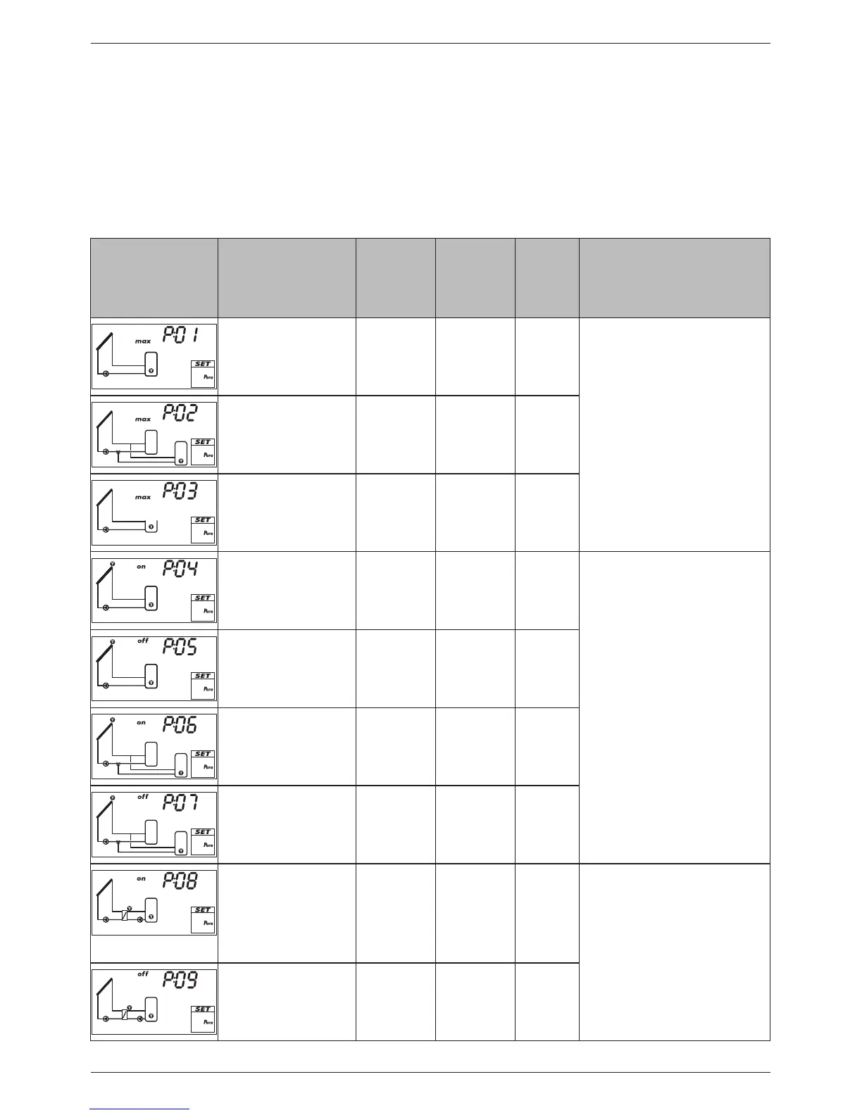
Display Parameter min. max.
Factory
setting
Functionality
Maximum tempera-
ture storage tank 1
0 °C 95 °C 60 °C When the maximum tem-
perature is exceeded, no more
loading occurs until the tem-
perature drops to 3 K below
the set value.
Maximum tempera-
ture storage tank 2
0 °C 95 °C 60 °C
Maximum tempera-
ture swimming pool
10 °C 45 °C 30 °C
Switch-on tempera-
ture difference solar
circuit 1
T
P05
+ 2 K 50 K 8 K When the switch-on tem-
perature difference between
collector and storage tank is
reached, the storage tank is
loaded.
Loading ends when the
switch-off temperature differ-
ence is reached.
Switch-off tempera-
ture difference solar
circuit 1
0 K T
P04
– 2 K 4 K
Switch-on tempera-
ture difference solar
circuit 2
T
P07
+ 2 K 50 K 8 K
Switch-off tempera-
ture difference solar
circuit 2
0 K T
P06
– 2 K 4 K
Switch-on tempera-
ture difference exter-
nal heat exchanger
T
P09
+ 2 K 50 K 6 K When the switch-on tempera-
ture difference between the
secondary side of the external
heat exchanger and the
storage tank is reached, the
storage tank is loaded.
Switch-off tempera-
ture difference exter-
nal heat exchanger
0 K T
P08
– 2 K 3 K Loading ends when the
switch-off temperature differ-
ence is reached.