44 742.892 | 11.50
EN
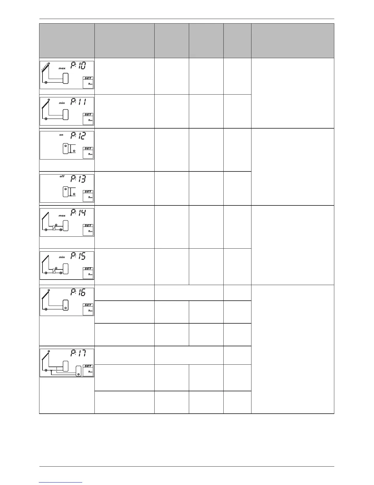
Display Parameter min. max.
Factory
setting
Functionality
Maximum collector
temperature
T
P11
+ 20 K 180 °C 130 °C When the maximum collector
temperature is exceeded, no
more loading occurs until
the temperature drops to 3 K
below the set value.
Minimum collector
temperature
0 °C T
P10
– 20 K 0 °C Load only starts when the
minimum collector tempera-
ture is exceeded.
Switch-on tempera-
ture difference heat-
ing return increase
T
P13
+ 2 K 50 K 6 K The heating return increase is
switched on (switching valve
on) when the switch-on tem-
perature difference between
the storage tank and heating
return temperature is reached.
Switch-off tempera-
ture difference heat-
ing return increase
0 K T
P12
– 2 K 3 K When the switch-off tem-
perature difference is reached,
the heating return increase is
switched off.
Maximum tempera-
ture loading circuit
T
P15
+ 20 K 130 °C 100 °C The difference between P14
and the temperature of the
secondary side of the heat
exchanger controls the solar
circuit pump and the storage
tank loading pump.
1)
Minimum tempera-
ture loading circuit
0 °C T
P14
– 20 K 0 °C The storage tank loading
pump is only switched on
when the secondary side of
the heat exchanger is greater
than or equal to P15.
Loading strategy
storage tank 1
dIFF
2)
, AbS
3)
The loading strategy depends
on the storage tank system
used and the usage of the
system.
diff: Highest efficiency. The
control target is the tem-
perature difference between
the collector and the storage
tank.
4)
AbS: Useful when the system
requires particular tempera-
tures, e.g. to avoid switching
on the external back-up heat-
ing system.
The control target is the tem-
perature of the collector.
4)
Control target of dif-
ferential temperature
loading (dIFF)
2 K 50 K 8 K
Control target of
absolute temperature
loading (AbS)
0 °C 95 °C 60 °C
Loading strategy
storage tank 2
dIFF
2)
, AbS
3)
Control target of dif-
ferential temperature
loading (dIFF)
2 K 50 K 8 K
Control target of
absolute temperature
loading (AbS)
0 °C 95 °C 60 °C