6 742.892 | 11.50
EN
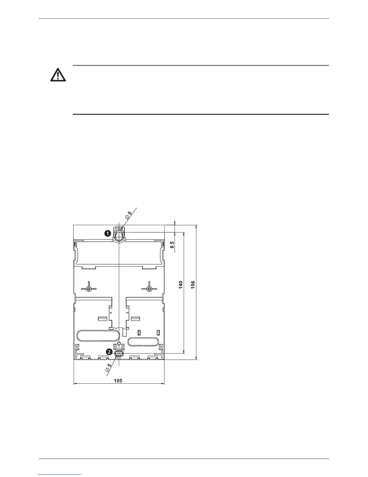
3.2 Mounting the casing
√ The mounting location must satisfy the prescribed conditions of use; more informa-
tion on this is provided in Section 14, p. 50.
√ The mounting surface is vertical and allows good access for installation.
Danger
Risk of death by electrocution!
• Disconnect the controller from the power supply before opening the casing.
• Make sure that the power supply cannot be unintentionally switched on when the
casing is open.
• Do not use the casing as a drilling template.
1. If necessary, remove the terminal cover
2. Screw in the screw for the upper mounting hole (Fig. 2) until the screw head has
a clearance of 5 ... 7 mm from the mounting surface.
3. Hang the controller on the screw by the upper mounting hole and align it vertically.
4. Mark the position of the lower mounting hole through the casing.
5. Remove the controller and prepare the mounting hole for the lower screw.
6. Hang the controller by the upper mounting hole and then fasten the screw in the
lower mounting hole .
7. Mount the terminal cover.
Fig. 2: Rear side of the controller with the upper and lower mounting holes