9742.892 | 11.50
EN
3.3.2 Preparing the cable openings
The cables can be fed through openings in the rear wall of the casing or at the bottom
of the casing. The openings are pre-punched and must be prepared as required before
installation.
Prepare the cable openings in the rear wall of the casing as follows:
1. Break out the cable openings (Fig. 3) using a suitable tool.
2. Deburr the edges.
Prepare the cable openings at the bottom of the casing as follows:
1. Cut the required cable openings (Fig. 3) at the left and right using a suitable knife
and break them out.
2. Deburr the edges.
3.3.3 Connecting the cables
√ All cables are voltage-free.
√ The cable openings have been prepared.
X Observe the following points when connecting the cables:
• Connect the cable conductors to the correct terminals as described in Section 3.4,
p. 10.
• Mains input and outputs: First connect PE, then N and L.
• Strain relief:
– First clamp the lower strain relief clamps and then the upper strain relief clamps.
– When using the upper strain relief clamps, use the plastic links as described
below.
– If the opening in the strain relief clamp is too large, e.g. in the case of thin ca-
bles, turn over the strain relief clamping bar (with the bend facing down).
– Only use the strain relief clamps for cables entering the bottom of the casing.
Use external strain relief clamps when feeding cables through the rear of the
casing.
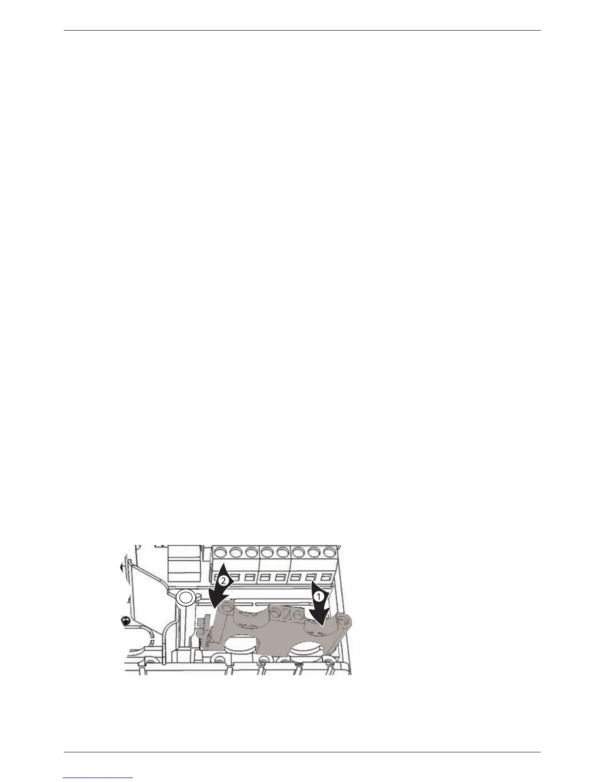
3.3.4 Inserting/Removing plastic links
Insert the plastic links as follows:
1. Insert the right plastic strip with the latching protrusion first (Fig. 4).
2. Press the other side of the plastic strip down , until the spring clamp latches into
place.
3. Insert the left plastic strip the other way around (latching protrusion to the left,
spring clamp to the right).
Fig. 4: Inserting the right plastic link