8 742.892 | 11.50
EN
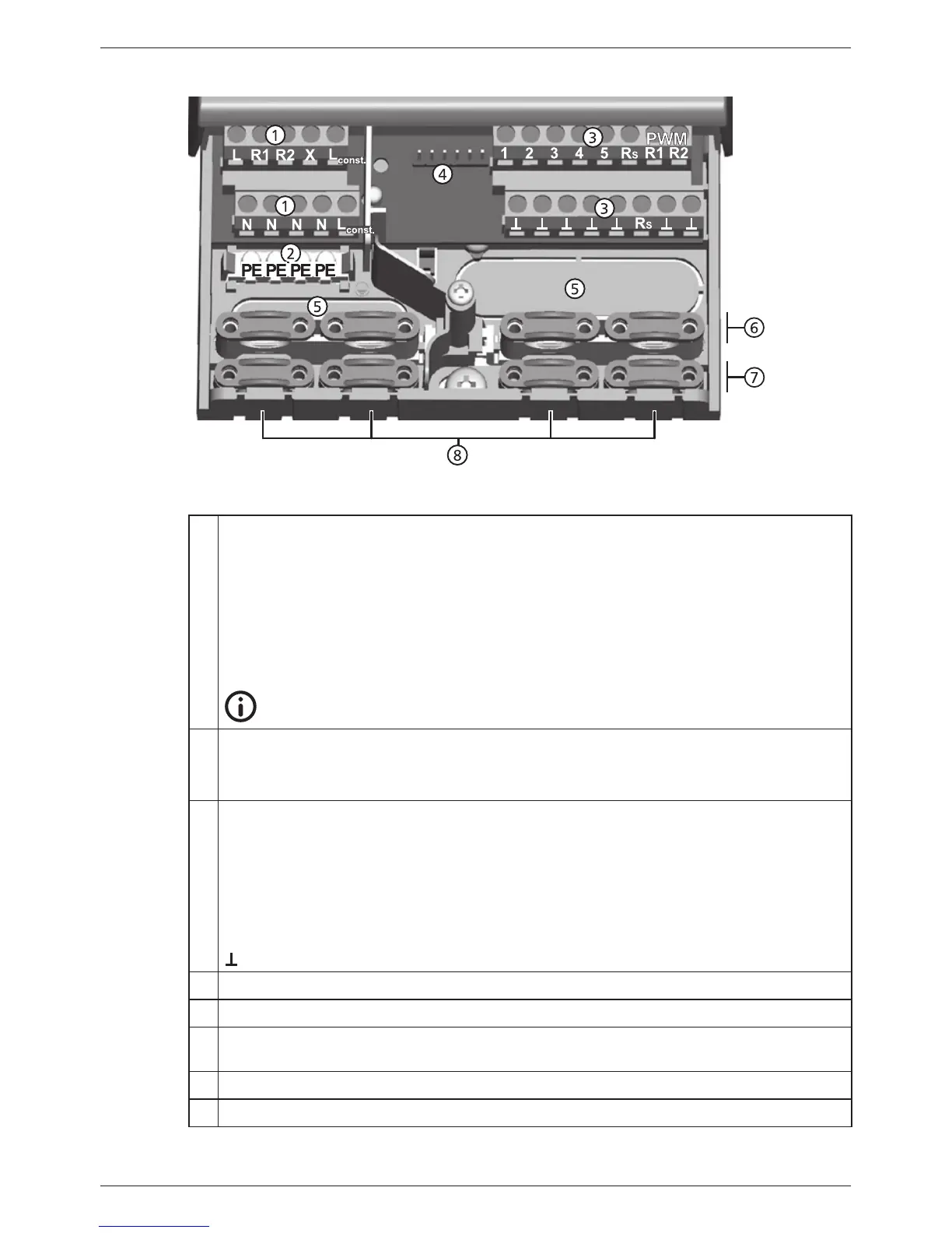
3.3.1 Position of the connection terminals
Fig. 3: Terminal clamps in the lower part of the controller (terminal cover removed)
Power connection terminal block
L
1x phase conductor (mains input)
R1, R2 2x output (TRIAC, for pumps or valves)
X
not used
L
const.
2x phase conductor (outputs, permanent voltage)
N
4x neutral conductor (common neutral conductors for mains power input
and outputs)
Note
Outputs R1 and R2 are protected by an electronic fuse.
Protective conductor terminal block:
PE
4x protective earth (common protective earth for power connection)
terminal block
Signals terminal block:
1 – 4 4x sensor input (Pt1000 temperature sensor)
5
1x sensor input (Pt1000 temperature sensor or pulse water meter input)
R
S
1x signal output (potential-free relay contact for safety extra-low voltage)
PWM R1
PWM R2
2x control output (for PWM-controlled high-efficiency pumps)
7x mass connection (common mass for sensor inputs and control outputs)
Pin strip, for internal use only
Cable openings on the rear side of the casing
Upper strain relief clamps (2 identical plastic links, each with 2 strain relief clamps,
supplied in the scope of delivery)
Lower strain relief clamps
Cable openings at the bottom of the casing