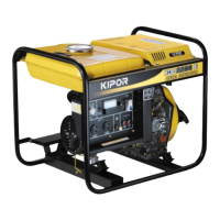
4.3 Generator
4.3.1 Generator
Check
(1) Front end cover: Check for cracking
(2) Generator fan: (Take care not to damage the fan blade in disassembling and
assembling)
(3)Rotor: Remove engine oil and contaminant on surface part before
installation. Normal measured resistance should comply with table 2.9. The color
should be red brown. In case of burn-out by short circuit, it would become black
and cracking would present. Then the rotor should be replaced.
(4)Clip ring: It should be smooth without any defect or distortion. The semicircle of
center boss should be clear. In case of distortion the clip ring should be replaced.
(5)Through stud: Locking torque is 50-55 Nm. If locked not tightly, the generator
would be damaged by scrubbing of rotor and stator.
(6)Stator: Check the external enamel covered wire for defect in disassembling
and assembling. Do not contact the copper wire part with ground or sharp metal
part directly to prevent scuffing.
(7)Stator lead-out: Divided into main winding, secondary winding, sampling
winding and 12V low voltage winding. Checkout the resistance of each winding, it
should be same as the parameter in table 2.9. Otherwise the stator should be
replaced.
(8)Carbon brush: There should be no open-circuit between lug and pole of carbon
brush, and no short-circuit between two poles.
(9)Rear end cover: Check for cracking.
Disassembling/assembling
(1)Open the rear end cover for open-shelf generating set. Remove the cabinet,
cooling plate, left and right side plate, and muffler for quiet generating set.
(2)Remove the generator with wiring. In quiet generating set must remove the
induced draft hood, then remove the harness.
(3)Remove 4XM6X175M bolt of rear end cover.
(4)Take out the stator.
(5)Fix the rotor with a belt spanner, then remove 10MM flange bolt.
Caution: Never knock the nut or rotor with hammer etc.
(6)Remove the rotor with a flywheel drawer.
4.3.2 Installation of rotor
Caution: Remove the dust and oil pollution from the crankshaft and rotor part.
Check the magnetic part of rotor for attachment of metallic material or gasket.
(1)Insert the semicircle clip ring into key groove.
(2)Install the rotor on the crankshaft.
(3)Fix the rotor with a belt spanner, secure the 10MM flange bolt to specified
torque.
Tightening torque: 50 Nm (5.0 kgf.m, 37.5 lbf.ft)
4.3.3 Stator
If measured resistance exceeds above-mentioned specified value, check the
harness of generator. Replace the harness of generator if necessary. If the
harness of generator is regular, replace the stator assembly.
Secondary winding:
Checkout the resistance between two blue (green) terminals of four-position
connector. See table 2.9 for the resistance value.
If measured resistance exceeds above-mentioned specified value, check the
harness of generator. Replace the harness of generator if necessary. If the
harness of generator is regular, replace the stator assembly.
AC winding:
Checkout the resistance of main winding on four-position terminal board.
The resistance value between (red, white, green) terminals in 120V/240V
simultaneous output.
In 120V/240V selected output the resistance for (brown, black, red, blue)
terminals which are (L1, L2; R1, R2) respectively.
If measured resistance exceeds specified value in table 2.9, check the harness of
generator. Replace the harness of generator if necessary. If the harness of
generator is regular, replace the stator assembly.
12V low voltage winding:
Checkout the resistance between the green terminals on four-position connector.
If measured resistance exceeds specified value in table 2.9, check the harness of
generator. Replace the harness of generator if necessary. If the harness of
generator is regular, replace the stator assembly.
Sampling winding:
Checkout the resistance between the yellow terminals on four-position connector.
If measured resistance exceeds specified value in table 2.9, check the harness of
generator. Replace the harness of generator if necessary. If the harness of
generator is regular, replace the stator assembly.
B. Adjustment
The spacing between the stator winding and rotor.
Insert a feeler between the stator winding and the projection of rotor. Push the
rotor winding to 90 , 180 , 270 , 360 . The rotor rotate for one turn. Secure
the flange bolt connecting stator and front end cover. The locking torque is 10-13
Nm (1.0 kgf.m, 7.5 lbf.ft). Spacing: 0.25 +/- 0.1 mm (0.020+/-0.004 in)