Press Force Sensor
Type 9323AA, 9323A, 9333A, 9343A, 9363A, 9383A, 9393A
Page 46 9323A_002-476e-11.24
7.1.1.3 Load application
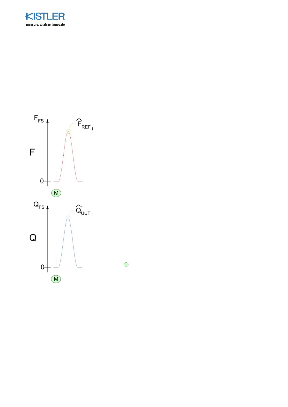
A typical load cycle is shown in Fig. 34.
1. The system must be in an unloaded condition to define
the zero force bias;
2. Reset the charge amplifiers and, if necessary, the peak
hold functions for both the reference and test system
measurement channels.
3. Apply the load to the required working point and then
back to the unloaded condition.
4. Record the peak values from the reference as well as
the test-system read-outs.
Reference system
F [MU] Force signal
F
PS
[MU] Measurement range (Full Scale) for reference
system charge amplifier
F
REFi
[MU] Reference system output for load cycle i
[MU] Peak value measured by the reference
measurement chain (for cycle i)
Test system
Q [pC] Charge signal
Q
PS
[pC] Measurement range (Full Scale) for test sys-
tem charge amplifier
Q
UUTi
[pC] Test system output for load cycle i
[pC] Peak value displayed on the test system
readout (for cycle i)
Reset charge amplifiers, start of measurement
Fig. 35: Load cycle definition
Detailed Steps for the in-situ calibration of a typical test
system is shown in Fig. 35 and the Calibration Process
Worksheet on the following page.
 Loading...