— 14 —
(Reference)
Rail width Inside trolley frame Outside trolley frame
50 H-steel Right/left, 8 pcs. each Right/left, 8 pcs. each
68
H-steel
Right/left, 11 pcs. each Right/left, 5 pcs. each
I-steel
98 H-steel
Right/left, 16 pcs. each Right/left, 0 pcs. each
100 I-steel
: Incorrect number of adjusting spacers may cause the trolley not to move or to
drop. To avoid these hazards:
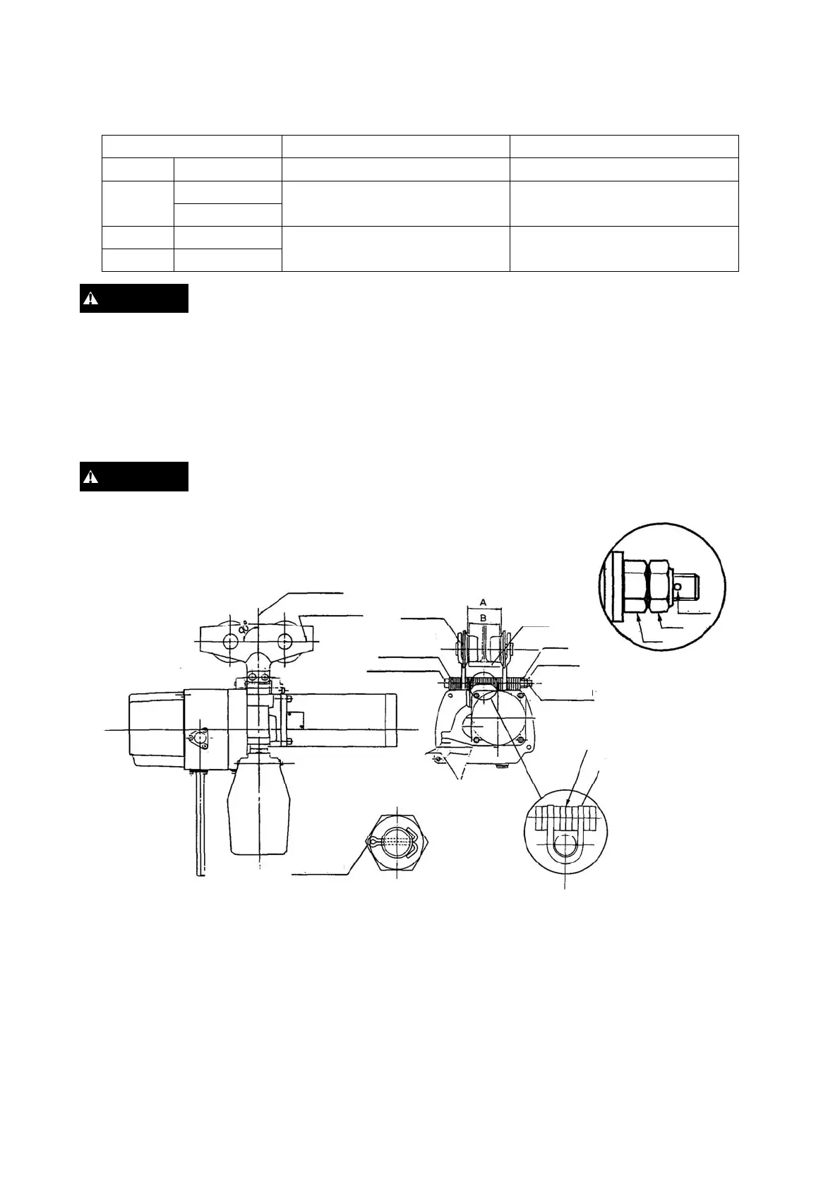
ALWAYS make sure to use all 32 pieces and confirm that A-B ≒ 3 mm.
* Fitting of socket bolt
Set the trolley so that the wheel axis is right angle to the load line. Attach the socket bolt, nut and U nut
(double nut system), adjusting the clearance of 2mm or less between the split pin hole and U nut with 2
Adjusting Spacers and 2 Adjusting Spacer-Bs, and then tighten them and secure the split pin to the bolt.
: To avoid the trolley from dropping, firmly fasten the socket bolt, nut and U
nut. Insert split pin and bend its ends 90° or more.
WARNING
WARNING
Load line
Split pin
U nu
Nut
Wheel axis
Trolley
frame
Rail
djusting
spacers
Socket bolt
Nut
U-nut
Split pin
Insert 4 adjusting spacers inside
the top yoke.
Top yoke
(of electric chain hoist)
Split pin
 Loading...