29
EN
7. Attach the 4 wire ropes to the cover and use the locking nut to secure the cover to
the suspension board. (See image 5). Note that the hole for the power cable on
the cover plate should be in the same direction as the hole for the power cable on
the cooker bonnet.
Image 5
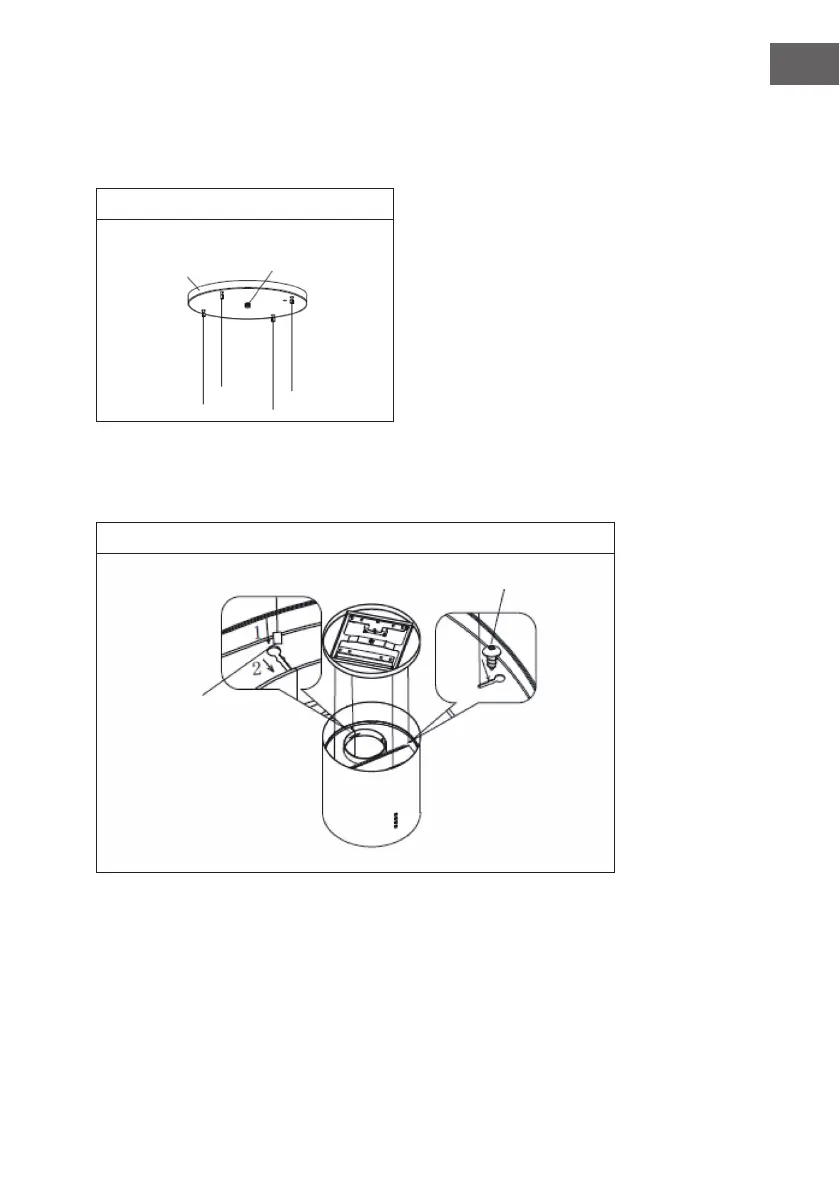
8. Follow steps 1 and 2 on image 6 to insert the 4 wire ropes into the slot of the top
plate of the cooker bonnet and use four countersunk screws (ST4*8 mm) to x the
wire ropes and prevent them from slipping out again (see image 6).
Image 6
Lock nut
Decorative
Cover
Insert the wire ends (1) and
push them forward into the
slot (2)
Countersunk screw