Dwg Name: CL700-1390105ART
Dwg No:
1390105
21122 Rev: B
1290186
9
FUNCTION BUTTONS
MAX/MIN
When the "MAX/MIN" button
8
is pressed, the meter keeps track
of the Maximum and Minimum values and the difference between
the Maximum and Minimum values as the meter continues to take
samples.
1. When measuring, press "MAX/MIN" button
8
to toggle between
the Maximum value (MAX) and the Minimum value (MIN). If a
new Maximum or Minimum occurs, the display will update with
the new value.
2. Press "MAX/MIN" button
8
for more than one second to return to
normal measuring mode.
NON-CONTACT VOLTAGE TESTING
Press the NCV button
12
to test for AC voltage using the integrated
non-contact voltage meter. Approach the conductor under test
leading with the sensing antenna
14
. The meter delivers visual
warning signals when AC voltage is detected.
TEST LEAD HOLDER
When working with test leads, one test probe may be mounted in the
test lead holder
13
to facilitate natural two-handed operation with the
clamp in one hand and a single test probe in the other.
OPERATING INSTRUCTIONS
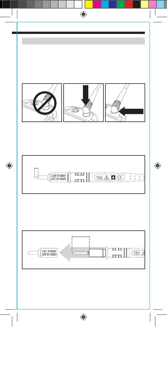
CONNECTING TEST LEADS
Do not test if leads are improperly seated. Results could cause
intermittent display readings. To ensure proper connection, firmly
press leads into the input jack completely. Lead guard should be
flush with the meter’s faceplate.
TESTING IN CAT III / CAT IV MEASUREMENT LOCATIONS
Ensure the test lead shield is pressed firmly in place. Failure to use
the CAT III / CAT IV shield increases arc-flash risk.
TESTING IN CAT II MEASUREMENT LOCATIONS
CAT III / CAT IV shields may be removed for CAT II locations. This
will allow testing on recessed conductors such as standard wall
outlets. Take care not to lose the shields.
PRESS
NO GAP
5/32"
(4 mm)
.7" (18 mm)
CL700-1390105ART.indd 9 12/4/2015 2:25:00 PM