4 5
ENGLISH
WARNINGS
To ensure safe operation and service of the meter, follow these instructions.
Failure to observe these warnings can result in severe injury or death.
• Before each use, verify meter operation by measuring a known voltage.
• DO NOT use the meter on a circuit with voltages that exceed the category
based rating of this meter.
• DO NOT use the meter during electrical storms or in wet weather.
• DO NOT use the meter or test leads if they appear to be damaged.
• Use ONLY with CAT IV rated test leads.
• Ensure meter leads are fully seated, and keep fingers away from the metal
probe contacts when making measurements.
• DO NOT open the meter to replace batteries while the probes are connected.
• Use caution when working with voltages above 25V AC RMS or 60V DC.
Such voltages pose a shock hazard.
• To avoid false readings that can lead to electrical shock, replace batteries
when a low battery indicator appears.
• DO NOT attempt to measure resistance or continuity on a live circuit.
• Make sure the circuit under test does not include components that can
be damaged by 1000VDC; such devices include power factor correction
capacitors, low voltage mineral insulated cables, electronic light dimmers,
and ballast/starters for fluorescent lamps.
• DO NOT perform insulation resistance testing or earth-bond resistance
testing if voltage is present on parts of an installation or equipment under
test. Circuits under test (except for voltage measurements) must be
de-energized and isolated before connections are made.
• Circuit connections must not be touched during a test. Accidental contact
with conductors could result in electrical shock.
• After insulation resistance testing, make sure the circuit is fully discharged
before removing test leads. LCD should read close to zero volts.
• Always adhere to local and national safety codes. Use personal protective
equipment to prevent shock and arc blast injury where hazardous live
conductors are exposed.
• Meter is IP40 dust & water resistant, except for the test lead jacks.
Following any contact with water, thoroughly dry meter and test lead jacks
prior to subsequent use.
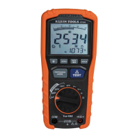
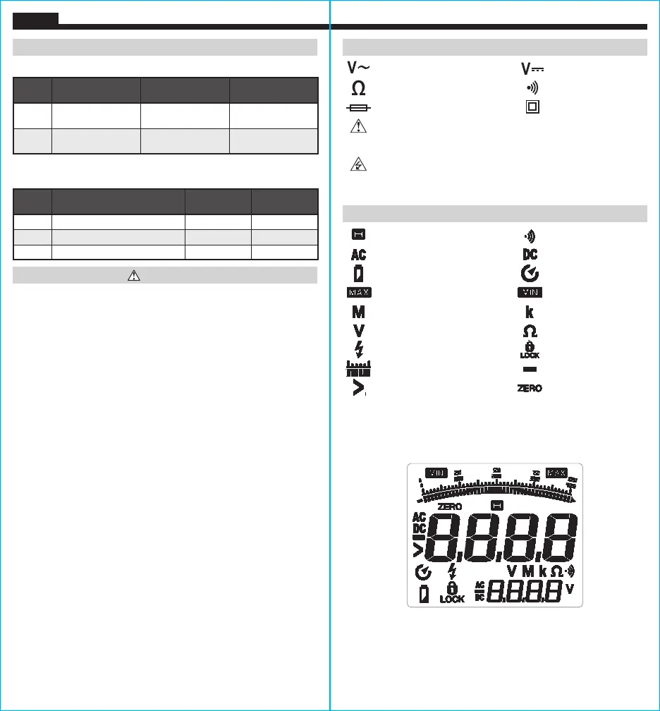
SYMBOLS ON METER
AC Voltage DC Voltage
Resistance (Ohms) Audible Continuity
Fuse (with rating below symbol) Double Insulated Class II
Warning or Caution
To ensure safe operation and service of this meter, follow all warnings
and instructions detailed in this manual.
Risk of Electrical Shock
Improper use of this meter can lead to risk of electrical shock. Follow
all warnings and instructions detailed in this manual.
SYMBOLS ON LCD
Data Hold Audible Continuity
AC (Alternating Current) DC (Direct Current)
Low Battery Auto Power Off
Maximum Value Minimum Value
Mega (value x 10
6
) kilo (value x 10
3
)
Volts Ohms
Test Voltage Test Lock
Bar Graph Negative
Greater Than Zero Adjustment
NOTE: The bar graph provides a visual indication of the measurement
value, showing voltage for VAC / VDC, and showing resistance for
insulation resistance testing.
INFLUENCE VARIABLES AND UNCERTAINTIES (EN61557)
Code Variable Range
% Within
Range
E1 Position
+/- 90°
<5%
E2 Supply voltage
7.21 to 9.13V
<5%
E3 Temperature 0 to 35°C <5%
OPERATIONAL UNCERTAINITY
INTRINSIC UNCERTAINITY (EN61557)
Code
Measurement
Intrinsic
Operating
Uncertainty
Maximum
Uncertainty*
A
Insulation
Resistance
See ELECTRICAL
SPECIFICATIONS
<30%
A
Earth-Bond
Resistance
See ELECTRICAL
SPECIFICATIONS
<30%
*Indicates maximun amout allowable by standard