8 9
ENGLISHENGLISH
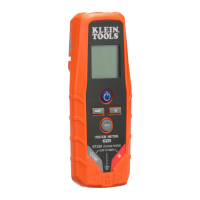
OPERATING INSTRUCTIONS
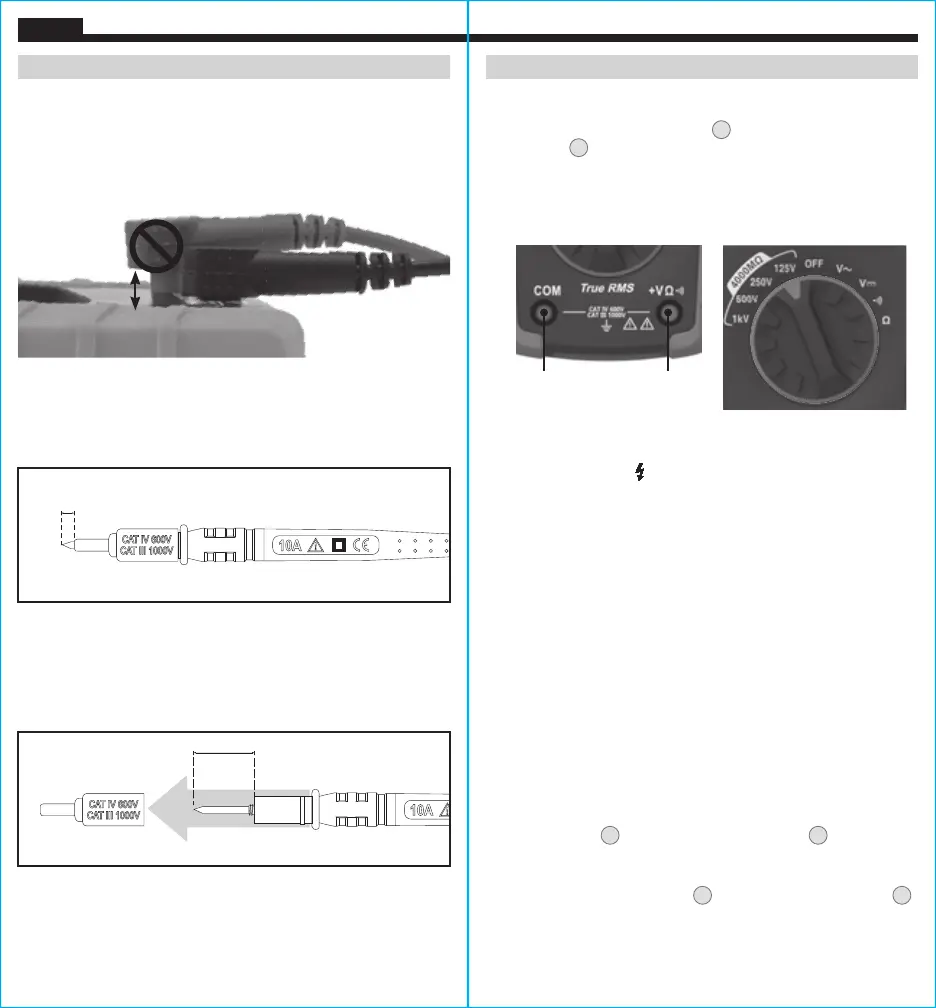
CONNECTING TEST LEADS
Do not test if leads are improperly seated. Results could cause
intermittent display readings. To ensure proper connection, firmly
press leads into the input jack completely.
TESTING IN CAT III / CAT IV MEASUREMENT LOCATIONS
Ensure the test lead shield is pressed firmly in place. Failure to use
the CAT III / CAT IV shield increases arc-flash risk.
TESTING IN CAT II MEASUREMENT LOCATIONS
CAT III / CAT IV shields may be removed for CAT II locations. This
will allow testing on recessed conductors such as standard wall
outlets. Take care not to lose the shields.
5/32"
(4 mm)
.7" (18 mm)
INCORRECT
CORRECT
OPERATING INSTRUCTIONS
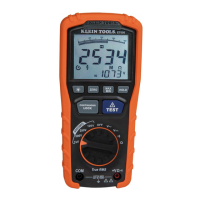
INSULATION RESISTANCE MEASUREMENTS
1. Insert RED test lead into VΩ jack
4
, and BLACK test lead into
COM jack
3
, and rotate the function selector to the desired test
voltage. Choose from 125V, 250V, 500V, or 1000V based on the
compatibility with the device tested.
NOTE: Disconnect the circuit
under test and isolate it from any stray resistance. Insulation test
should only be performed on de-energized circuits.
2. Connect the Red and Black leads to the circuit under test. If there
is a voltage in the circuit, a constant beep will sound and the
Test Voltage symbol will be displayed.
Disconnect the circuit to
proceed.
3. Press and hold the TEST button to begin test. The lower right
display shows test voltage, and the main display shows the
resistance.
4. The measured insulation resistance is displayed on the main
display in MΩ. Allow the reading to stabilize before recording the
measurement. Turning the function switch, at any time during
the insulation test will end the testing process.
5. The circuit will discharge through the meter. Keep the test leads
connected until the circuit is completely discharged and the
lower right display shows near zero volts.
NOTE: Measurements can be adversely affected by impedances
of additional operating circuits connected in parallel or by transient
currents.
LOCK FUNCTION
For hands free testing, use the Lock feature.
With the test leads connected to the equipment under test, press
the "LOCK" button
9
, then press the "TEST" button
10
to begin the
test. The lock icon will appear on the display. The meter will beep
to indicate it is in lock mode. To end the test at any time during the
process, press the "TEST" button
10
, or turn the function switch
2
to any other setting.
Red leadBlack lead