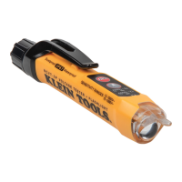
10 11
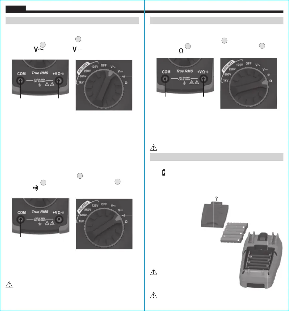
FUSE REPLACEMENT
1. Remove screw from
battery/fuse door.
2. Replace blown fuse
with 6.3 x 31.7 mm,
500mA/1000V
fast-blow 10kA fuse
(Klein Cat. No. 69035).
3. Replace battery/fuse door and
fasten securely with screw.
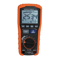
OPERATING INSTRUCTIONS OPERATING INSTRUCTIONS
ENGLISH
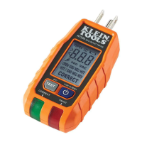
MAINTENANCE
BATTERY REPLACEMENT
When
indicator is displayed on LCD, batteries must be replaced.
1. Remove screw from battery/fuse door.
2. Replace 6 x 1.5V AA batteries (note proper polarity).
3. Replace battery/fuse door and fasten securely with screw.
To avoid risk of electric
shock, disconnect leads from
any voltage source before
removing battery/fuse door.
To avoid risk of electric shock, do not operate
meter while battery/fuse door is removed.
CONTINUITY
1. Insert RED test lead into VΩ jack
4
, and BLACK test lead
into COM jack
3
,
and rotate function selector switch
2
to the
Continuity
setting.
2. Remove power from circuit.
3. Test for continuity by connecting conductor or circuit with test
leads. If resistance is measured less than 40Ω, an audible signal
will sound and display will show a resistance value indicating
continuity. If circuit is open, display will show "OL".
DO NOT attempt to measure continuity on a live circuit.
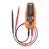
Red leadBlack lead
RESISTANCE MEASUREMENTS
1. Insert RED test lead into VΩ jack
4
, and BLACK test lead
into COM jack
3
,
and rotate function selector switch
2
to the
Resistance setting.
2. Remove power from circuit.
3. Measure resistance by connecting test leads to circuit. The
meter will auto-range to display the measurement in the most
appropriate range.
NOTE: When in a Resistance setting and the test leads are open
(not connected across a resistor), or when a failed resistor is under
test, the display will indicate O.L. This is normal.
DO NOT attempt to measure resistance on a live circuit.
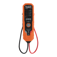
Red leadBlack lead
AC/DC VOLTAGE MEASUREMENTS
1. Insert RED test lead into VΩ jack
4
, and BLACK test lead
into COM jack
3
, and rotate the function selector to the
AC Voltage or DC Voltage setting.
2. Apply test leads to the circuit to be tested to measure voltage.
NOTE: When measuring DC voltage, the main display shows the
voltage measurement, the secondary display shows battery voltage.
NOTE: When measuring DC voltage, if "–" appears on the LCD, the
test leads are being applied to the circuit in reverse polarity. Swap
the position of the leads to correct this.
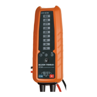
Red leadBlack lead