49
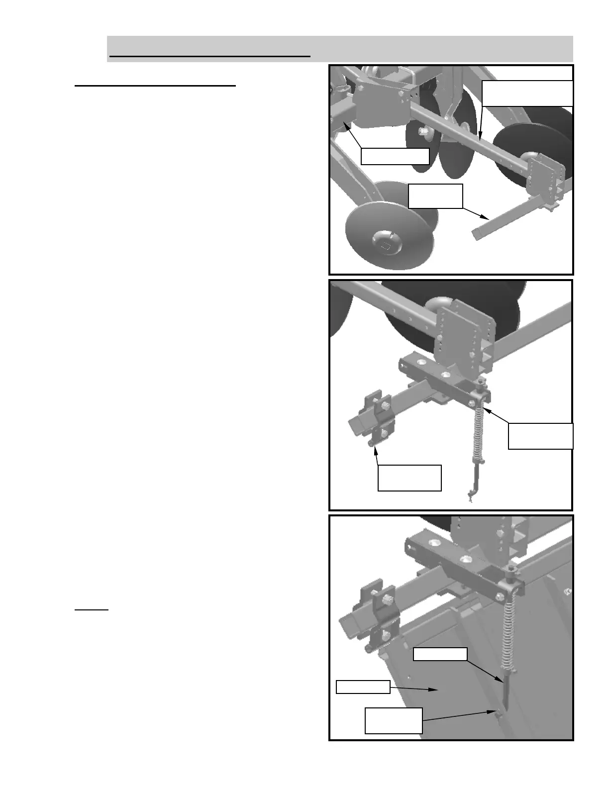
Bedder Door Assembly:
1. Attach 4 x 4 Bedder Door Reaches
(06-082-165) to the rear of the 4 x 4 Tool Bar
using (2) 7/8 x 6 1/2 capscrews, lockwasher,
hexnuts and a Reach Arm Cap (11-023-019)
for each reach. Position the reaches so that
they clear the area where the Door Pressure
Bundle mount. Do not tighten reach to bar
until they are in the correct position.
2. Next mount the 2 1/2 x 2 1/2 tool bar to the
rear of the 4 x 4 Bedder Door Reach
(06-082-165) using (2) 5/8 x 3 1/2 capscrew,
lockwashers, hexnuts and a P.B.Clamp Cap
(02-023-188)
3. Now assemble Door Pivot (06-082-053) on
each end of the 2 1/2 x 2 1/2 tool bar using
(2) 5/8 x 3 capscrews, lockwashers, hexnuts
and a P.B. Clamp Cap (02-023-188). Do not
tighten Door Pivots until your Door is located
in the correct position.
4. Hang your Bedder Door in the Door Pivot
tubes as shown in the pictures. Once the Door
is located in the correct position tighten
capscrew in the Door Pivot and the Bedder
Door Reaches.
5. Mount the Door Pressure Bundle
(06-082-054) on each end of the 2 1/2 x 2 1/2
Tool Bar using (2) 5/8 x 4 1/2 Carriage
Screws, lockwashers, hexnuts, and a P.B.
Clamp Cap (02-023-188). Do not tighten into
position until you have attached the spring
rods to the Bedder Door and held them into
place with a 3/16 x 1 1/2 Cotter Pin.
Bedder Door Reach
(06-082-165)
4 x 4 Tool Bar
2 1/2 x 2 1/2
Tool Bar
Door Pressure
(06-082-054)
Door Pivot
(06-082-053)
Bedder Door
3/16 x 1 1/2
Cotter Pin
Spring Rod
BEDDER DOOR OPTIONS:
NOTE: Refer to the “Overhead Layouts”
portion of this section, for the correct position-
ing of all the above components. See the
layout pages for the size and row pattern of
your purchased unit.
For Stackfold Bars, note the bedder doors on
the wings are staggered back to allow stacking
clearance. Refer to the “Overhead Layouts”
portion of this section for an example.
 Loading...