KMS MD35 manual
Version 4.16 13
Inductive sensor: consists of coil around constantly magnet. The change in magnetic field generates
a current in the coil. When a tooth passes the coil with magnetic core the magnetic field changes.
When a tooth is approaching the signal gets stronger. When a tooth is passed the signal gets weaker.
Difference is the Hall sensor generates a Voltage and the inductive sensor generates a current.
TIP: Measure the resistance between two pins by using a multimeter. When sensor is inductive the
resistance should be between 0.5kΩ and 2 kΩ. When the sensor uses a 3 pole connecter there should
also be the resistance of 0.5kΩ – 2 kΩ between two pins. The remaining pin is the shield of the
sensor cable. If resistance is not measurable the sensor will be likely a Hall effect sensor.
Warning:
Do not use unsuppressed spark plugs and leads. They can cause
electromagnetic interference.
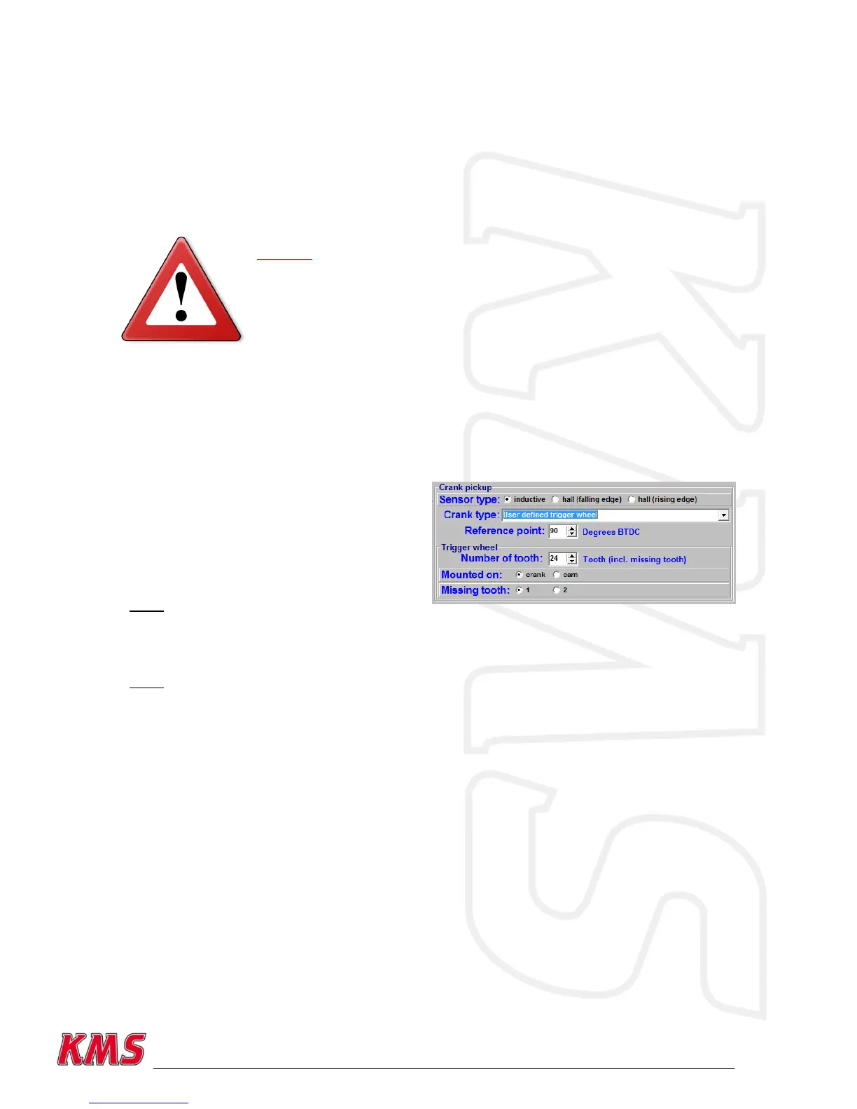
Crank-type:
The rpm signal has to be delivered by an hall/inductive sensor using a rotating trigger pattern. The
individual pattern types are listed under the pulldown menu, possible combinations are listed in this
table. Some trigger patterns are shown in Appendix 1: Trigger pattern drawings.
It‟s also possible to configure your own trigger
pattern when choosing the „User defined trigger
wheel‟. You can specify the number of tooth of
the triggerwheel. This number must be an equal
number and must lie between 24 and 72 tooth.
You can also choose to mount the trigger wheel
on the crank- or camshaft and choose to make
the reference point 1 or 2 missing tooth.
Note: It‟s still only possible to use one
reference point.
When using the „User defined trigger wheel‟, the number of coils (ignition outputs used on the
MD35) and odd fire TDC‟s (see chapter 3.2.4.1.1.3) must be defined.
Note: When using a 60-2 trigger pattern the maximum engine speed is limited to 12.500 rpm.
When using a Hall-sensor, it is nescessary to use a convertor that will change the Hall-signal into an
inductive signal (exception below). The convertor has KMS partnummer 01-01-07-0333.
A Hall-sensor crank pickup can be used directly without convertor on the cam pickup signal input
pin 34 (see section cam pickup below). „Direct fire‟ is disabled because a cam signal is needed and
there is only cam signal input which is used by the hall sensor. To keep direct fire enabled together
with a Hall-sensor crank pickup, it is nescessary to use a convertor that will change the Hall-signal
into an inductive signal. The convertor has KMS partnummer 01-01-07-0333.
Reference point:
The reference point (the position of the piston at the moment the first tooth after the missing
tooth/teeth passes the sensor) of the crank pickup sensor can be set between 0 and 180 degrees
before TDC (for most engines recommended between 70 - 120degrees). The position of the
reference point in the software must be checked. Mark the TDC on the crankshaft pulley or
flywheel. Check with a timing light the degrees when igniting on cylinder 1 in TDC with a static
engine speed. If the ignition advance set in the software deviates from the measurement with the
timing light, than you have to correct the reference point in the software.