KMS MD35 manual
Version 4.16 15
Important is that the cam reference point is not set on the edge of the (missing) tooth, but as far as
possible in the centre of the (missing) tooth. With the pattern on the right in the figure above, it‟s
impossible to set the cam reference point in the middle of the tooth. When the sensor is positioned
in the middle, 360 crank degrees later, the signal will be the same. The top tooth is wider than the
bottom tooth. The cam reference should be set in the middle of this extra width.
3.2.4.1.1.3 Coil on time
A coil should be charged before every discharge (plug spark). The coil charging time is indicated in
ms. It should normally be 1.4 to 3.5 ms depending on the type of coil. Longer coil charging leads to
unnecessarily high power consumption and heat development, shortening the service life of the coil.
Warning:
The coils can only be operated via a driver circuit. If the computer is
connected to the coil directly, the ECU can get damaged beyond repair.
Many modern coils feature a built-in driver stage. However, if a coil without
an integrated driver stage is used, the separate KMS ignition driver module
with partnumber 01-01-04-0001 will be needed.
Dis-coil:
The choice is between dis-coil (wasted spark) and single coil control (rotor and distributor cap). If
you have a dis-coil (and also when using coil per plug wasted spark) the box has to be ticked.
Direct-firing:
This option detects the compression stroke which enables you to ignite directly on one cylinder at a
time (you have to connect the cam sensor to make this work). With dis-coil it is a wasted spark.
Separate coils per cylinder is requiered for this sequential ignition. Make sure that the connections
of the KMS ECU to the single coils are in the right igniting order. For example a 4 cylinder inline
engine with firing order 1-3-4-2. The coil outputs get activated in the order 1-2-3-4. For direct-firing
coil output 1 fires cylinder 1, coil output 2 fires cylinder 3, coil output 3 fires cylinder 4 and coil
output 4 cylinder 2.
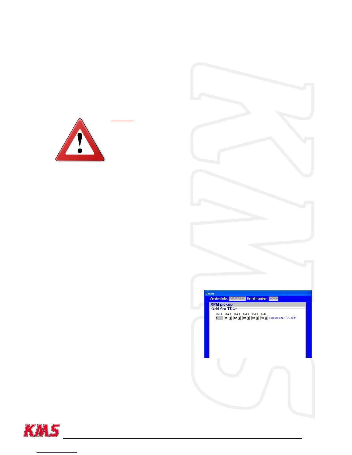
Odd fire TDCs:
You can advance/retard the ignition time for every
cylinder. This can be useful at assymetrical engines.
You have to fill in the angles of different cyliders. The
degrees must be ascending with a maximum of 360
degrees. How to determine the odd fire TDC‟s for a V6:
First check what the engine firing order is. The cylinder
that is in TDC and where the reference point is set to is 0
degrees. Devide the number of cylinders in the right firing
order evenly over 720 degrees (= 2 rotations for 4 stroke).
The cylinders on the same crankpin but later in the firing
order and different bank have to be corrected for the angle
of the block. So the degree for these cylinders isn‟t on the degree calculated before when deviding
720 dregrees through all cylinders but the angle of the block. The degree for the second cylinder on
the same crankpin is the sum of the degrees from the first cylinder on the same crankpin and the
angle of the block.
In the software you can fill in a maximum of 360 degrees after TDC so you have to subtract 360
degrees from the cylinders which have higher degrees than 360 (this is needed in case of a
camsensor failure to keep the engine running on all cylinders but as a wasted spark).