EasyManua.ls Logo

KMS Simplekey 4 - Reader Interface Overview

Default Icon
52 pages
Print Icon
To Next Page IconTo Next Page
To Previous Page IconTo Previous Page
Loading...
Key Management Systems Ltd 38 | P a g e
Reader Interface Overview
KMS BUS
1
2
12V
0V
1
2
3
1
2
3
SIG
LED
LED
SIG
CH2
CH1
CH1 &
CH2
Set reader mode for each channel KMS or
Wiegand. Default SET TO OFF = KMS
S2M
LED
M2S
LED
1
2
3
4
5
6
7
8
Note: Due to space considerations on the PCB, reader terminations
are labelled 1 through to 3 for each channel.
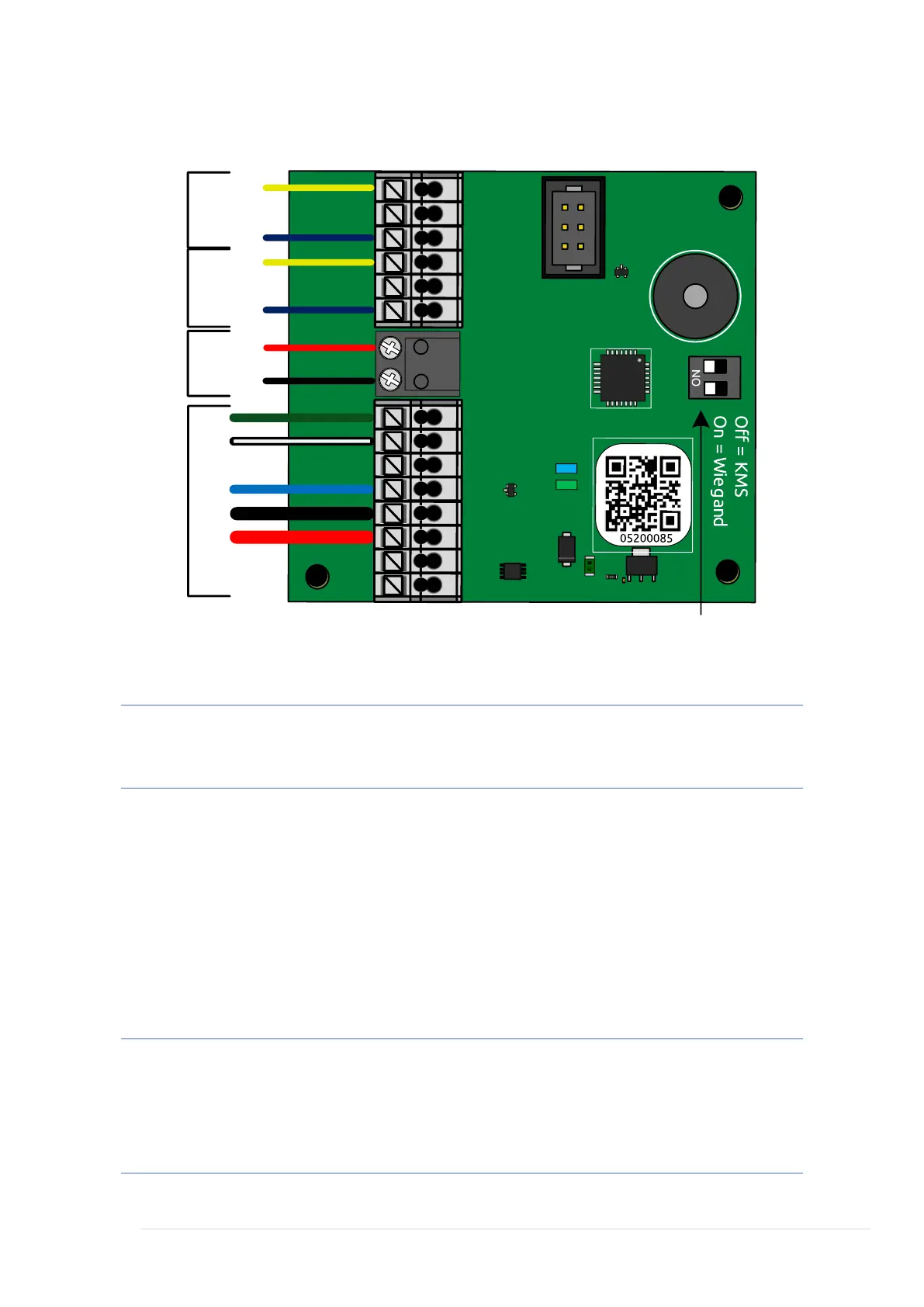
Reader Connections A and B
1. LED/Speaker
2. Wiegand Data 0
3. SIG/Weigand Data 1
12v. Shared output for Ch1 & Ch2
0v. Shared output for Ch1 & Ch2
Note: Only one reader can be wired into each channel, where a read
IN and read OUT configuration is required, a separate Reader
Interface will be required per door. Refer to Technical Support for
further information.

Table of Contents