Key Management Systems Ltd 44 | P a g e
System Wiring Example 1
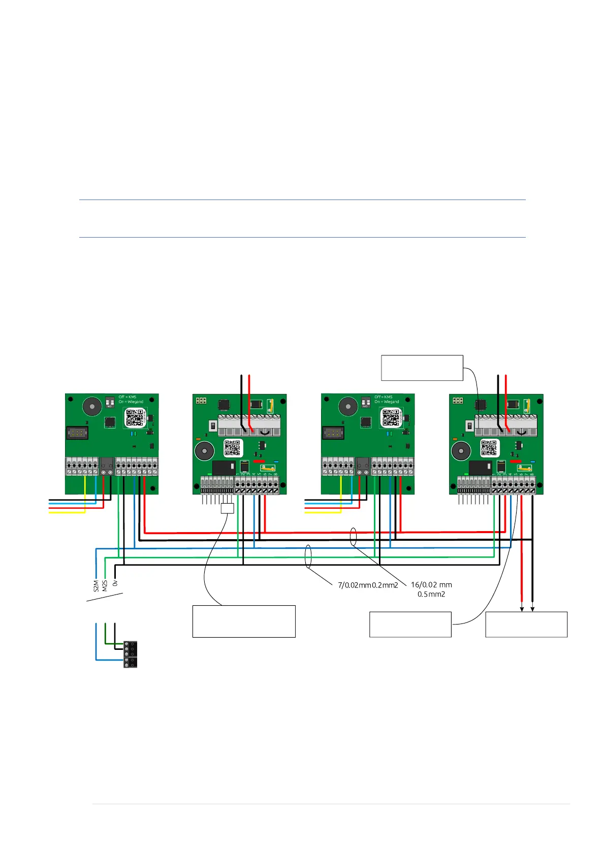
This image shows a system wired to its local power supply with KMS BUS data
connections direct to the System Controller.
In this example KMS are powering the locks directly. This is the recommended
installation configuration. Each Lock Controller does provide a normally
open/normally closed volt free relay in order to trigger external equipment, for
example a powered door closer or door entry system.
Note: Always isolate power before making or breaking connections.
Typical example of daisy chained Reader Interfaces and Lock Controllers utilising local
power supplies within each cabinet. This assumes the System Controller is in a
separate cabinet with BUS runs of M2S, S2M and 0v back to the System Controller or
next cabinet. Ensure BUS runs are made using Cat5, Cat5e or Cat6 cabling. Copper
only no CCS or CCA to be used.