TP-6049 9/02 31Section 6 Installation
Fuel Conversion Procedure for Multi-Fuel
Systems
1. Place the generator set master switch in the OFF
position.
2. Disconnect the power to the battery charger, if
equipped.
3. Disconnect the generator set engine starting
battery, negative (--) lead first.
4. Turn off the fuel supply.
5. Remove the hose clamp and fuel hose from the
hose fitting in the fuel block. See Figure 6-7.
6. Remove the hose fitting from the natural gas (or
LP) outlet port in the fuel block.
7. Remove the plug from the LP (or natural gas) port
in the fuel block. Clean the plug with a dry cloth or
brush, apply fresh pipe sealant, and install the plug
into the natural gas (or LP) outlet port.
8. Clean the hose fitting with a dry cloth or brush,
apply fresh pipe sealant to the threads, and install
the fitting into the LP (or natural gas) port.
Note: Do not adjust the fuel metering valves.
9. Slide the hose onto the hose fitting and secure it
with the clamp.
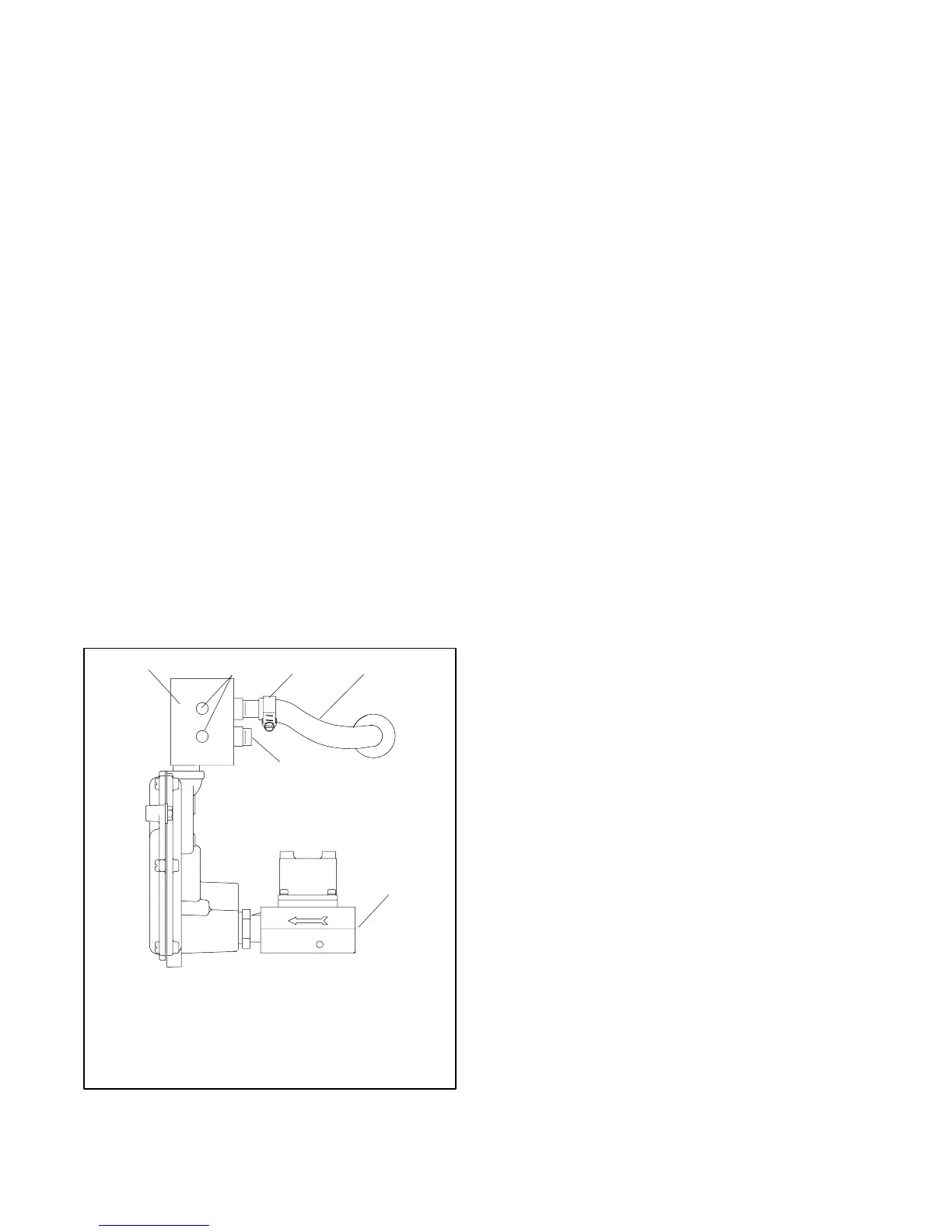
5
ADV-6600
1. Fuel block
2. Fuel metering valves—factory-sealed, do not adjust
3. Clamp
4. Fuel line hose
5. Plug
6. Fuel inlet, 1/2 in. NPT
OUT IN
LP
NG
1
42
6
3
Figure 6-7 Fuel Block Connections, Natural Gas
System Shown
10. Connect the new fuel supply.
11. Turn on the fuel supply and check for leaks using a
gas leak detector.
12. Check that the generator set master switch is in the
OFF position.
13. Reconnect the generator set engine starting
battery leads, negative (--) lead last.
14. Reconnect power to the battery charger, if
equipped.
6.8 Electrical Connections
6.8.1 Accessory Electrical Connections
Some accessories, including a run relay and a common
fault relay, can be connected to the generator set.
Contact an authorized service distributor/dealer for a list
of accessories.
Have the accessories installed by an authorized
distributor/dealer or a licensed electrician. Follow the
installation instructions provided with each kit. Most
accessories operate on 12 volts DC; some may require
AC line voltage. Use separate conduit for AC and DC
leads to reduce the possibility of electrical interference.
Verify that the leads and conduit do not interfere with the
operation of the generator set or obstruct the service
areas. Verify that the electrical installation complies with
the National Electrical Code (NEC) and all applicable
local and state codes. See Section 5, Wiring Diagrams,
for more information regarding generator set electrical
connections.
 Loading...


