TP-6049 9/02 29Section 6 Installation
6.7 Fuel System
The generator set operates using natural gas or LP
vapor fuel. The multi-fuel system allows conversion
from natural gas to LP vapor (or vice-versa) in the field
while maintaining emissions-standard compliance. A
trained technician or authorized distributor/dealer can
convert the fuel system. Generator sets with multi-fuel
systems are CARB- and EPA-certified for both natural
gas and LP vapor fuels.
6.7.1 Fuel Supply
Comply with local, state, and federal codes regarding
the correct storage of fuel. Because of variable climates
and geographical considerations, c ontact an authorized
service distributor/dealer for fuel system planning and
installation. Figure 6-2 shows the location of the fuel
inlet connection, the fuel and electric stub-up area, and
the rear panel access holes. Bring the fuel supply lines
through either the bottom or the rear access openings.
Protect all fuel lines from machinery or equipment
contact, adverse weather conditions, and environmental
damage.
Verify that the output pressure from the primary gas
utility (or LP tank) pressure regulator is 1.7--2.7 kPa
(7--11 in. water column) and that the utility gas meter
flow rate is sufficient to supply the generator set plus all
other gas-consuming appliances. Figure 6-3 shows the
flow rate required for the generator set. Contact the
natural gas utility for flow rate information or a gas meter
upgrade.
6.7.2 Fuel Pipe Size
Ensure that the natural gas pipe size and length meet
the specifications in Figure 6-4. Measure the pipe
length from the primary gas pressure regulator to the
pipe connection on the generator set fuel inlet. Add
2.4 m (8 ft. ) to the measured length for each 90 degree
elbow. Compare the pipe size and length with the chart
in Figure 6-4. If the piping is longer than the maximum
length shown for that size, replace it with the specified
size before proceeding.
Contact the local LP provider for LP installation
information.
Generator Set Model Gas Flow Rate, Btu
hr.
8.5RMY 132,000
11RMY 192,000
12RMY 202,000
Figure 6-3 Natural Gas Flow Rate
Maximum Pipe Length m (ft.)
Pipe Size
8.5RMY 11RMY 12RMY
3/4 in. NPT 18.3 (60) 9.2 (30) 9.2 (30)
1 in. NPT 61 (200) 30 (100) 30 (100)
1 1/4 in. NPT 91.5 (300) 68.6 (225) 68.6 (225)
Figure 6-4 Maximum Natural Gas Pipe Length
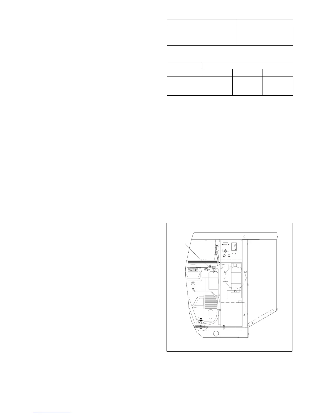
6.7.3 Single-Fuel Systems
Generator sets with single-fuel systems are equipped
with the fuel valve shown in Figure 6-5 and have
specification numbers starting with PA-.
Single-fuel generator sets that have the decal shown in
the Introduction section are emission-certified. The fuel
systems on emission-certified single-fuel generator sets
are not field-convertible or adjustable. The factory sets
the fuel system for the specified fuel and seals it to
prevent adjustments.
Note: Do not adjust or convert the fuel system on an
emission-certified single-fuel generator set.
Changing the fuel or adjusting the fuel systems
on these units may violate federal or state laws.
TYPE ABC
F1 10 AMP
AUTOOFF
RESET/
RUN
F2 10 AMP
TYPE ABC
ON
OFF
P-358000-C
1
1. Fuel valve
Figure 6-5 Single-Fuel Generator Set Fuel Valve
Location
 Loading...


