TP-6049 9/02 37Section 6 Installation
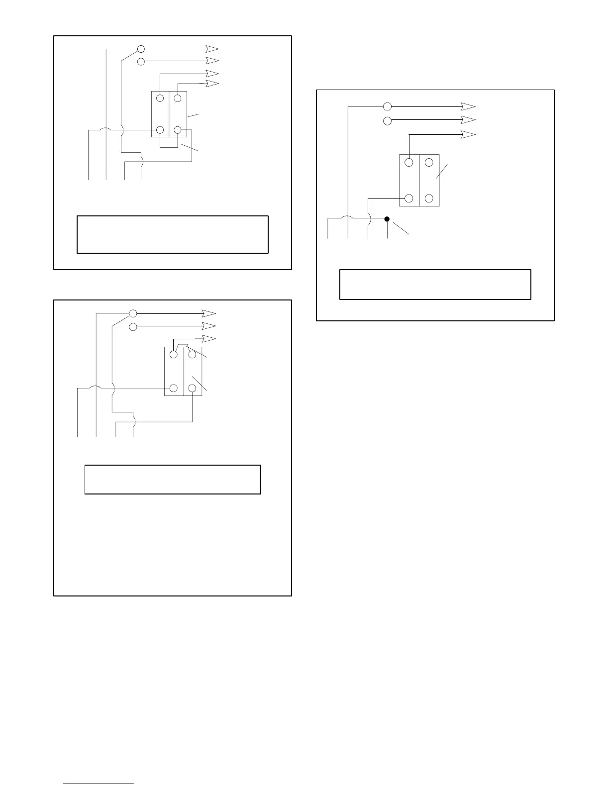
43 21
Stator Leads
LO
GRD
LO (Neutral)
Ground
Load
Side
Line
Side
Factory two-pole
circuit breaker
Field installed
jumper lead
L1
L2
TP-5867
L0-L1
L0-L2
60 Hz
120 volt
120 volt
50 Hz
110 volt
110 volt
Figure 6-16 110 and 120 Volt, 3-Wire Configurations
Note: The existing ammeter lower scale indicates
half of the actual L1 current. DO NOT PUT
THE CT ON L1. Either label the ammeter
with a note indicating lower scale times two,
or purchase a new ammeter scaled twice the
existing ammeter and install the new
ammeter.
4321
Stator Leads
LO
GRD
LO (Neutral)
Ground
Load
Side
Line
Side
Two-pole
circuit breaker
L1
TP-5867
L0-L1
60 Hz
100--120 volt
50 Hz
110--120 volt
Field installed
jumper lead
Figure 6-17 110 and 120 Volt, 2-Wire Configurations
220 and 240 Volt Configuration
A jumper lead is not used. After connection adjust the
voltage regulator to obtain the desired voltage.
4321
Stator Leads
LO
GRD
L1
LO (Neutral)
Line
Side
Factory two-pole
circuit breaker
Ground
Load
Side
Tape to insulate
from ground
TP-5867
L0-L1
60 Hz
240 volt
50 Hz
220 volt
Figure 6-18 220 and 240 Volt, 2-Wire Configurations
6.10 Prestart Installation Check
Review the entire installation section. Inspect all wiring
and connections to verify that the generator set is ready
for operation. Check that there are no obstructions to
the air inlet and outlet.
Complete the startup procedure and installation
checklists supplied with the startup notification form.
Return the form to the distributor/dealer or mail it directly
to:
Kohler Power Systems
Generator Warranty Administrator
M.S. 072
Kohler, Wisconsin 53044
 Loading...


