TP-6735 7/1728 Section 3 Troubleshooting
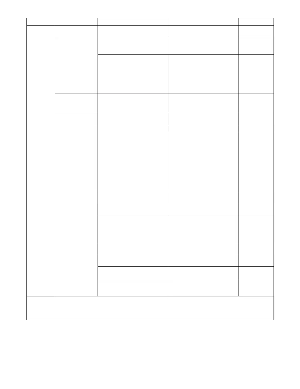
Problem Possible Cause Test Corrective Action Reference
Generator
set engine
does not
crank
Battery connections Check for reversed or poor
battery connections.
Correct and tighten battery
connections.
—
Weak or dead
battery
Test the battery voltage.
Test battery according to battery
manufacturer’s recommendations.
Recharge or replace battery. O/M
If battery is weak or dead, check
the battery charger.
Check battery charger fuse and
connections.
Check 120VAC power supply to
the charger.
Test charger operation.
Tighten connections and replace
charger fuse if blown.
Connect 120VAC power to
charger.
Replace charger if necessary.
O/M
Open circuit in
engine/controller
connections
Check for loose connections.
Check the wire harness continuity.
Tighten connections.
Replace harness or harness leads
if damaged.
Section 5.13
Section 7
Blown controller
fuse F3
Use a test lamp or meter to check
fuse F3.
Replace fuse; if fuse blows again,
check circuit and components.
Section 5.14.2
Section 7
Blown fuse F2 Use a test lamp or meter to check
fuse F2.
Replace fuse. Section 5.14.2.
If fuse blows again, disconnect
the following leads. Reconnect
one at a time and attempt to start
to identify the cause of the blown
fuse:
Lead 70A at the fuel valve
Lead IGN at the ignition module
Lead 71A at the starter relay
Leads FP and FN at the rotor
Repair or replace the component
causing the blown fuse.
Section 7
Crank relay K3 on
controller circuit
board
Check connections to the
controller.
Tighten connections.
Replace wiring if damaged.
Section 4.12
Check for a good ground
connection.
Tighten/repair ground connection.
Section 7
Check the crank LED to verify
12VDC to relay K3.
If the Crank LED is not lit, check
for 12VDC to the board.
If the Crank LED is lit but relay K3
does not operate, replace the
controller circuit board.
Section 7
Section 4.12
Poor ground (--)
connection
Test ground connection. Clean and retighten. —
Starter relay
Check connections to the starter
relay.
Tighten connections.
Replace wiring if damaged.
Section 1.7
Check continuity of circuit. Section 5.13
Section 7
Check that the starter relay picks
up when 12VDC is applied at lead
71A connection.
Replace starter relay.
Section 7
W/D = Wiring Diagram(s) (Section 7) S/S = Generator Set Specification Sheet O/M = Generator Set Operation Manual
I/M = Generator Set Installation Manual Engine S/M = Engine Service Manual
* RDC controller settings can be checked and adjusted using the controller user interface or using a personal computer running SiteTech
software. DC controller settings can only be changed using SiteTech.

 Loading...


