TP-6735 7/17 27Section 3 Troubleshooting
Section 3 Troubleshooting
3.1 Introduction
Corrective action and testing in many cases requires
knowledge of electrical systems and electronic circuits.
Have an authorized distributor/dealer or trained service
technician perform testing and service.
Refer to the engine service manual for engine service
information. See the List of Related Materials for the
document part number.
If the troubleshooting procedures in this section identify
a failed part, refer to the parts catalog for replacement
part numbers. See the List of Related Materials in the
Introduction for the parts catalog number.
3.2 Initial Checks
When troubleshooting, always check for simple
problems first. Check for the following common
problems before replacing parts:
D Loose connections or damaged w iring.
D Dead battery.
D Fault s hutdown. Check for a fault code on the
controller display. Section 4.8 describes the warning
and shutdown fault codes. If a fault code is displayed,
identify and correct the cause of the fault condition.
Then reset the controller.
D Blown fuses. Tw o controller fuses are located in the
controller’s service access area. See Figure 3-1. A
battery charger fuse is located in the positive battery
lead. Always check for and replace any blown fuses
before replacing other components. Identify and
correct the cause of the blown fuse. See
Section 5.14.2 for fuse part numbers.
D Incorrect controller settings. Always check the
controller configuration settings before replacing the
controller. Section 4.10 contains the instructions for
checking and changing the controller configuration.
D Inadequate fuel supply. Check for damaged
primary or secondary fuel regulators, loose
connections to the fuel solenoid valve, a damaged or
closed fuel shutoff valve, an empty LP fuel tank, or
other problems with the fuel supply. Check the fuel
supply pressure to the generator set. See
Section 5.11, Fuel Systems.
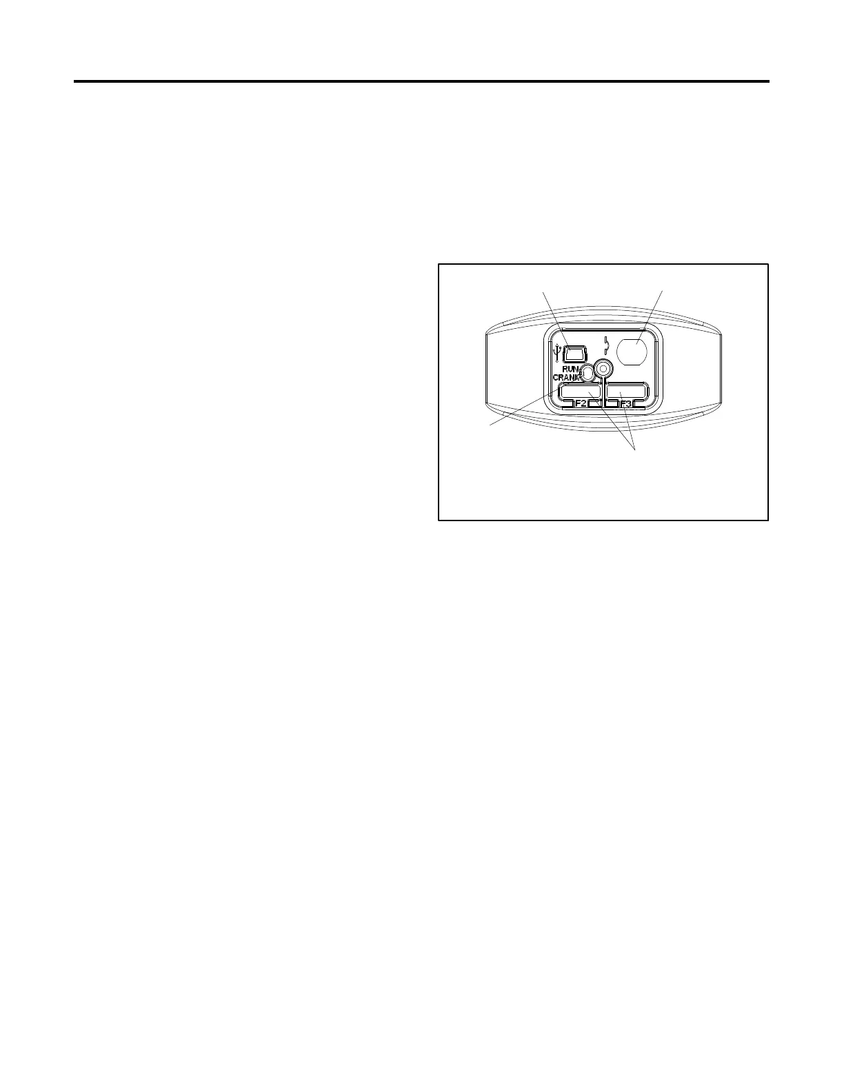
3.3 Controller Service Access
The controller fuses and alternator winding circuit
breaker are accessible from the front of the controller.
Remove the service access door to reach the circuit
breaker and fuses. See Figure 3-1.
Obtain replacement fuses from a Kohler authorized
distributor/dealer.
2
GM62860
1. USB port (for computer connection for SiteTech software)
2. Alternator winding circuit breaker
3. Controller fuses F2 and F3
4. Run and crank LEDs
1
3
4
Figure 3-1 Controller Service Access (cover
removed)
3.4 OnCue Troubleshooting
See TP-6796, OnCue Software Operation Manual, for
troubleshooting instructions for the OnCue Home
Generator Management System.
D The OnCue Ethernet option board must be installed
onto the RDC/DC controller for connection to the
Internet. See TT-1566.
D RDC/DC firmware version 3.0 or higher is required
for network communication.
3.5 Troubleshooting Chart
Use the following table as a reference in troubleshooting
individual problems. Generator set faults are listed in
groups and include likely causes and remedies. The
simplest and most likely causes of the problem are listed
first; follow the recommendations in the order shown.
The reference column provides additional sources of
information in this and related manuals regarding the
problem and solution.

 Loading...


