TP-6735 7/17 39Section 4 Controller
4.4.1 LED Display
When the system is in AUTO and the generator set is not
running, the L ED display shows the engine run time
hours. During cranking, the display shows the crank
cycle information.
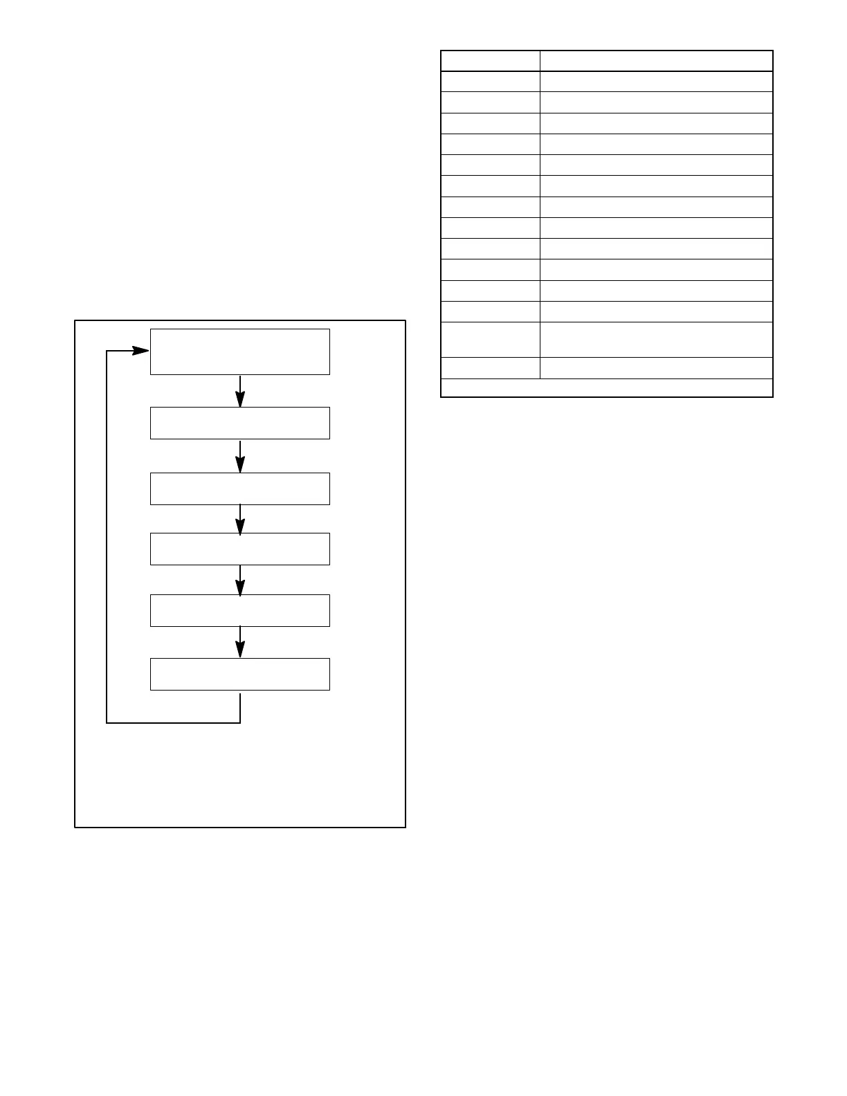
When the generator is running, the display steps
through the status messages shown in Figure 4-3, as
applicable. The generator set must be connected to a
Model RRT transfer switch for the utility voltage display.
When a fault or warning condition exists, the controller
will show the respective message. The following table
shows the various generator conditions and expected
display or messages.
D Generator set is running.
D Model RRT transfer switch is required for utility voltage
display.
D Display steps through the parameters in sequence for
2 seconds each.
tp6734
Engine Runtime
XXX.X or XXXX hours
Utility Voltage
UXXX VAC
Engine Temperature
tXXX
Battery Voltage
bXX.X VDC
Generator Voltage
EXXX VAC
Test or exercise mode,
if applicable.
tnLd, t LD, EnLd, or E Ld
Figure 4-3 Data Displays, Generator Running
Display Description
Blank (dark) Controller is off.
u#.# Controller software version number
XXX.X Engine hours to 999.9
XXXX Engine hours, 1000 to 9999
bXX.X Battery voltage
tXX.X Engine temperature
UXXX * Utility voltage
EXXX Generator voltage
tnLd * Test, no load
tLd* Test, loaded
EnLd Exercise, no load
ELd* Exercise, loaded
CC1,2,or3 Engine crank cycle 1, 2, or 3. Flashes
during crank pause.
Fault code Warning or fault. See Figure 4-8.
* Model RRT ATS is required for this display.
Figure 4-4 RDC Controller Display
4.4.2 Controller Keypad
The Run, Off, Auto, and Down arrow or Exercise buttons
control the generator set as described in Figure 4-5.
See Section 4.5 for operation instructions.
RDC controller (RES models) only: The Select, Up,
and Down buttons on the controller keypad are used to
adjust the controller parameters. The system
configuration and performance is factory-set and
should not require changes under normal operating
conditions. To prevent inadvertent changes, a pass
code is required to access the controller parameter
settings. See the generator set Installation Manual for
controller configuration instructions. See Section 5.8 of
this manual for performance adjustment instructions.
For the DC controller (RESL models), a personal
computer with Kohlerr SiteTecht software is required
for system configuration changes and performance
adjustment.

 Loading...


