TP-6735 7/1772 Section 5 Component Testing and Adjustment
Hazardous voltage. Moving parts.
Will cause severe injury or death.
Operate the generator set only when
all guards and electrical enclosures
areinplace.
DANGER
Short circuits. Hazardous voltage/current will cause
severe injury or death. Short circuits can cause bodily injury
and/or equipment damage. Do not contact electrical
connections with tools or jewelry while making adjustments or
repairs. Remove all jewelry before servicing the equipment.
Hot engine and exhaust system.
Can cause severe injury or death.
Do not work on the generator set until
it cools.
WARNING
Governor System Operation Test Procedure
1. Verify that the carburetor throttle linkage is
connected to the stepper motor as shown in
Figure 5-16.
2. Look for broken or loose wiring or plug connections
if the stepper motor moves erratically. Check the
condition of the throttle linkage, and verify that the
throttle plate closes completely.
3. Check the operation of the stepper motor at
startup.
a. If the throttle moves to the fully open throttle
position and then steps to and remains in the
fully closed position, the engine speed input is
probably missing. The engine starts and then
shuts down on an overspeed fault. Proceed to
step 4 to c heck the magnetic pickup.
b. If the throttle linkage moves erratically or not at
all at during startup, proceed to step 6 to check
the stepper motor.
4. Stop the engine and check the resistance of the
magnetic pickup.
a. Stop the generator set. Remove housing
panels as required to gain access to the front of
the engine.
b. Remove the engine blower housing.
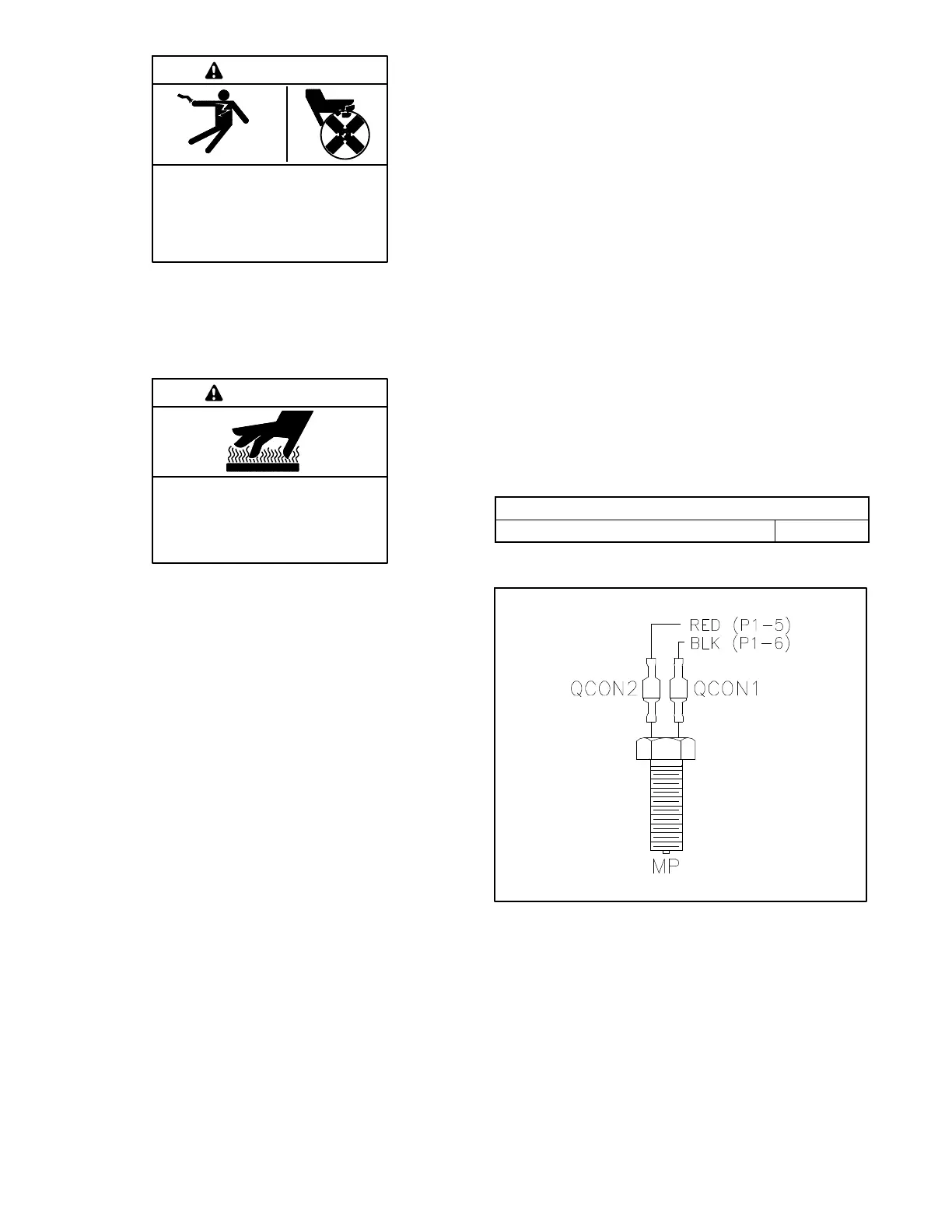
c. Disconnect the magnetic pickup at QCON1
and QCON2. The magnetic pickup must be
isolated from the generator controller to allow
an accurate resistance measurement.
d. Measure the electrical resistance through the
magnetic pickup at QCON1 and QCON2. See
Figure 5-19.
e. Compare the resistance measurement to the
value shown in Figure 5-18. If the resistance is
significantly higher (open circuit) or lower
(short circuit), replace the magnetic pickup.
f. Reconnect QCON1 and QCON2.
Magnetic Pickup Resistance
Resistance across QCON1 and QCON2 1.6 k
Figure 5-18 Magnetic Pickup Resistance
6519
Figure 5-19 Magnetic Pickup Leads

 Loading...


