TP-5982 4/06 23Section 4 Exhaust System
Waterline
7
14
13
12
15
10
9
8
18
11
19
6
17
4
5
20
16
1
2
3
21
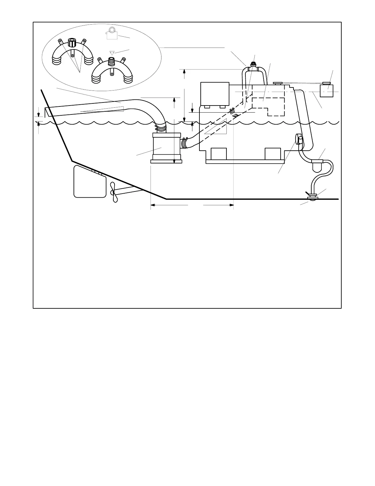
1. Mounting base
2. Retaining cap
3. Reed valve assembly
4. Maximum silencer vertical lift of 1.2 m (4 ft.)
5. Exhaust mixer elbow distance above the waterline. If less than
23 cm (9 in.), a siphon break is required.
6. Minimum siphon break distance above the waterline of 30.5 cm
(1 ft.)
7. Siphon break
8. Exhaust mixer elbow
9. Heat exchanger (locations vary by model)
10. Coolant recovery tank (located on unit on some models)
11. Indicates coolant recovery tank at same height as heat
exchanger
12. Seawater strainer
13. Seacock
14. Intake strainer
15. Engine-driven seawater pump
16. Minimum exhaust hose pitch of 1.3 cm per 30.5 cm (0.5 in. per
ft.)
17. Maximum distance between silencer and exhaust mixer elbow
of 3 m (10 ft.)
18. Silencer (customer supplied)
19. Minimum exhaust hose pitch of 1.3 cm per 30.5 cm (0.5 in. per
ft.)
20. Minimum exhaust outlet distance above waterline of 10 cm
(4 in.)
21. Exhaust hose size: 5cm (2 in.) ID
NOTE: Data applies to both rear- and side-exhaust installations.
Figure 4-11 Typical Mid and Below Waterline Installation
Note: Use two hose clamps on each end of all flexible
exhaust hose connections.
Note: Read the text for a complete explanation of
dimensions and other installation considerations.