TP-6376 3/0824 Section 1 Specifications and Features
0: System Options
Off
0) Select Temp Option
On
Degrees Fahrenheit
1) Select Temp Units
Degrees Celsius
Vertical
2) Select T
nk Orient
tion
Horizontal
Rectangular
3) Select T
nk Type
Cylindrical
US gallons
Press
4) Select Volume Units
Liters
select
Imperial gallons
Actual level (volume)
5) Select
olume
iewing
Percentage
6) Set Tank Volume Adjust to volume of tank (1000 default)
7) Lower Position Calibration
Set fuel level gauge to lower position. Set fuel level percentage that corresponds with
lower position used (0% default value). Press select to save.
8) Upper Position Calibration
Set fuel level gauge to upper position. Set fuel level percentage that corresponds
with upper position used (100% default value). Press select to save.
1: Trip Levels
0. Low fuel trip level Set to desired level (50% default value)
1. High fuel trip level Set to desired level (90% default value)
2. Critical Low fuel trip level Set to desired level (5% default value)
3. Critical High fuel trip level Set to desired level (95% default value)
4. Pump A ON trip level (0--100%) Set to desired level (70% default value)
5. Pump A OFF trip level (0--100%) Set to desired level (85% default value)
Press
6. Pump B ON trip level (0--100%) Set to desired level (55% default value)
select
7. Pump B OFF trip level (0--100%) Set to desired level (85% default value)
8. Reverse Pump ON trip level (0--100%) Set to desired level (95% default value)
9. Reverse Pump OFF trip level (0--100%) Set to desired level (85% default value)
10. Low Temperature trip level Set to desired level
11. High Temperature trip level Set to desired level
2: Status Relay Options
0. Pumps
ctive Rel
y
1. Ruptured B
sin Rel
y
2.
ow Fuel Rel
y
.
.
norm
y open
Press
3. High Fuel Rel
y
N.C.
norm
ll
closed
4. Critic
l
ow Rel
y
.
.
5. Critic
lHighRel
y
6.
l
rm Rel
y
3: Alarm Horn Options
0. Critic
l
ow Horn Option
1. Critic
l High Horn Option
2. Ruptured B
sin Horn Option
3. High Fuel Horn Option
4.
ow Fuel Horn Option
e
u
Press
5. Open
evel Sensor Horn Option
ON
6. Shorted
evel Sensor Horn Option
7. High Temper
ture Horn Option
8.
ow Temper
ture Horn Option
9. Open Temper
ture Sensor Horn Option
10. Shorted Temp Sensor Horn Option
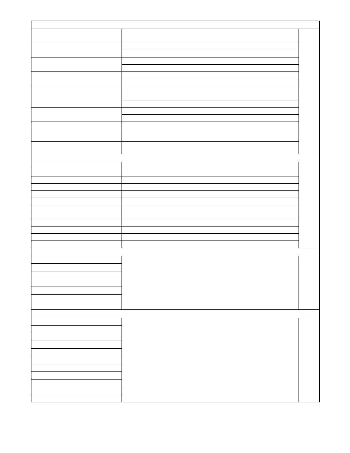
Figure 1-31 Tank Monitor Programming Flowchart