TP-6376 3/0846 Section 5 General Maintenance
5.5 Engine Oil Makeup System
This feature provides a means to replenish the engine
oil level during generator set operation. An engine will
normally use a small amount of oil over time and when
left unchecked will cause an engine shutdown. This
feature provides a convenient and reliable source of
makeup engine oil without user involvement.
Check and fill the engine oil makeup system reservoir
when the engine oil pan is filled during oil changes. The
oil makeup system reservoir capacity is approximately
9.5 L (2.5 gal.). The reservoir is located above the
engine and mounted to the enclosure. The oil level
regulator is located at the engine oil pan full level and
automatically provides makeup oil to the engine oil pan
by way of a one-way valve and gravity feed.
This feature does not replace the need for the user to
perform routine oil checks as recommended in
Section 4.2, Prestart Checklist, and Section 5.4,
Service Schedule.
Note: Close the valve at the oil level regulator inlet hose
to prevent overfilling the engine oil pan when
transporting the unit.
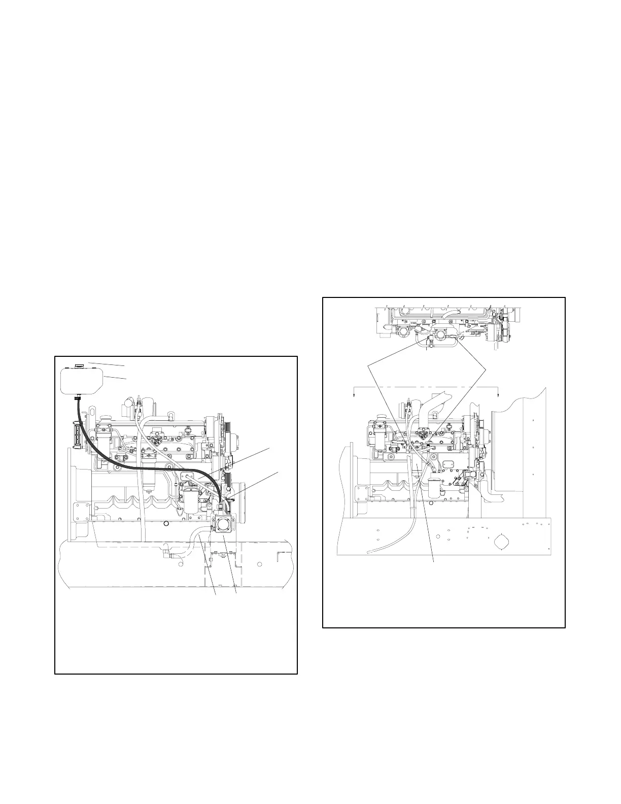
1. Oil makeup reservoir fill
2. Oil makeup reservoir located on the enclosure
3. Oil level regulator vent hose at engine block
4. Oil level regulator inlet hose with valve from oil makeup
reservoir (close when transporting the unit)
5. Engine oil level regulator
6. Oil level regulator outlet hose to oil pan drain connection
1
2
GM42866-B
3
4
5
6
Figure 5-1 Engine Oil Makeup System
(200KRP model shown)
5.6 Fuel/W ater Separator Bypass Kit
The fuel/water separator bypass kit provides the ability
the change the engine fuel/water separator element
while the generator set is running allowing uninterrupted
electrical power. The element replacement procedure
must be done promptly to minimize the chance of
particulate and/or water in the fuel from getting into the
fuel injection system. Change the element immediately
after activating the bypass system and return it to the
normal position as soon as the fuel/water separator is
cleaned and the element is replaced.
Use the fuel/water separator bypass k it even when the
unit is not running as it provides easy fuel shutoff and
minimizes air intrusion in the fuel system.
If the fuel/water separator bypass kit is installed on the
unit (see Figure 5-2), choose the fuel/water separator
element replacement procedure shown in Section 5.7
which corresponds accordingly.
1. Fuel/water separator outlet shutoff two-way valve
2. Fuel supply three-way valve
3. Fuel/water separator element
1
2
GM45888-A
AA
VIEW A-A
Partial View
3
Figure 5-2 Fuel/Water Separator Bypass Kit
(200KRP shown)