TP-6376 3/08 23Section 1 Specifications and Features
1.6.11 Fuel Tank and Fuel System
The fuel tank location varies by generator set model.
The 60--200KRP models have a fuel system with an
internal polymer tank below the enclosure. See
Figure 1-27 for specifications and see Figure 1-29 for
an illustration.
Item Specification
Engine fuel inlet 3/8 NPT
Engine fuel return 3/8 NPT
Fuel tank fill 2NPT
Fuel tank vent 2NPT
Figure 1-27 Fuel Tank, 60--200KRP
The 400KRP models use a secondary containment
steel fuel tank located inside the trailer. See Figure 1-28
and Figure 1-30 for an illustration.
Item 400KRP
Fuel tank capacity, L (gal.) 1893 (500)
Fuel tank fill 2NPT
Fuel tank inlet/return 1NPT
Fuel tank atmospheric vent (raised) 2NPT
Fuel tank rupture basin drain 1NPT
Figure 1-28 Fuel Tank and Fuel System, 400KRP
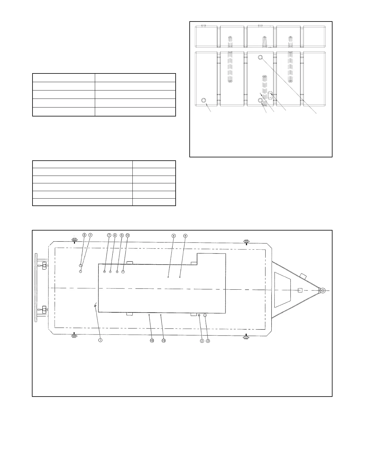
GM33838
1. Female aluminum molded insert, tank vent, 2 NPT
2. Hose insert, fuel supply, 3/8 in.
3. Hose insert, fuel return, 3/8 in.
4. Female aluminum molded insert, fuel fill, 2 NPT
5. Female aluminum molded insert, gauge, 2 NPT
14532
Figure 1-29 Fuel Tank Connections, 60--200KRP
1. 1/2 in. NPT for fluids drain
2. 1 1/2 in. NPT for level gauge
3. 2 in. NPT for fill
4. Two 4 in. NPT for emergency vent
5. 1 1/4 in. NPT for leak detection
6. 1 1/4 in. NPT for normal vent
7. 2 in. for low level switch
8. 1 in. NPT with 3/8 in. NPT diptube for fuel return
9. 1 in. NPT with 3/8 in. NPT diptube for fuel supply
SK1A-15926
Figure 1-30 Fuel Tank Connections, 400KRP