TP-6376 3/0836 Section 3 Electrical Connections and Requirements
3.4 Electrical Power Panel
The following information pertains to other available
electrical connections beyond the main load lugs. This
section shows a complete electrical connection list and
descriptions that may not apply to all models. Power
connections are user-selectable and vary with each
situation or application. See Figure 3-3, Figure 3-5, and
Figure 3-6 for electrical panel illustrations. Some
models offer ground fault circuit interruption (GFCI)
protection receptacles powered by the generator set.
3.4.1 Battery Charger Power Inlet
Use the power inlet on the power panel to connect an
external power supply to the generator set battery
charger.
3.4.2 Block Heater Power Inlet
Use the power inlet on the power panel to connect an
external power supply to the generator set block heater.
3.4.3 Circuit Breaker(s), Main
60--200KRP. The two main circuit breakers (main
disconnect) are 3-pole and protect the load lugs. The
208 to 240-volt circuit breaker protects the low wye or
single-phase voltage circuit. The 480-volt circuit
breaker protects the high wye voltage circuit. The
voltage selector switch determines which circuit breaker
controls the main load.
400KRP. A single circuit breaker with trip adjustment
required.
3.4.4 Circuit Breakers, GFCI
Receptacles
The circuit breakers are single-pole and protect the
GFCI receptacles on the power panel. One circuit
breaker controls one receptacle. The power panel
identifies corresponding circuit breakers and
receptacles.
3.4.5 Load Lug Assembly
Use the load lug assembly to attach user-supplied load
connections and/or distribution boxes.
3.4.6 Camlocks, 60--200KRP
One set of five (60/100KRP) or two sets (200KRP)
provide convenient attachment of user-supplied power
connections. Camlocks are colored-coded black, red,
blue, white, and green for identification and use with
three-phase voltages. Use the black, red, white, and
green camlocks for single-phase voltages. See
Figure 3-10.
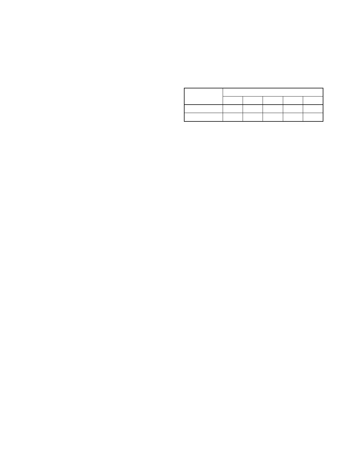
Camlock Colors (Left to Right)
Black Red Blue White Green
Single-phase X X X X
Three-phase X X X X X
Figure 3-10 Camlocks for Single- and Three-Phase
Connections
3.4.7 Duplex GFCI Receptacles
The power panel provides several 3-prong receptacles
for user convenience. The duplex GFCI receptacles
provide power when the generator set is running and the
voltage selector switch is in the single-phase or 208-volt
position.
Note: The duplex GFCI receptacles are not available
when the voltage selector switch is in the 480-volt
position.
3.4.8 Voltage Indicator Lamps
60--200KRP. Three lamps on the power panel indicate
main load lug voltage of 480 (high wye), 240 (single
phase), and 208 (low wye).
400KRP. Two lamps on the power panel indicate main
load lug voltage of 480 (high wye) and 208 (low wye).
The illuminated lamp indicates the generator set
configuration and voltage selector switch position.
In addition, the AC meter/LCD display on the generator
set controller provides main load lug voltage.