EasyManuals Logo

Kohler 6VSG Manual

Kohler 6VSG
58 pages
To Next Page IconTo Next Page
To Previous Page IconTo Previous Page
Page #15 background imageLoading...
Page #15 background image
TP-6843 7/15 Section 1 Descriptions and Service Views 15
1.7 Service Views
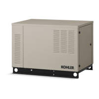
Figure 1-2
Figure 1-2 Service View (see Figure 1-3 for optional communications kit components)
1. Exhaust air outlet
2. Air cleaner
3. Oil fill
4. Oil drain
5. Oil drain valve
6. Oil filter
7. Muffler
8. Alternator air inlet
9. Customer connection blocks (located behind panel)
10. Electrical inlet access panel
11. Engine starting battery location (battery not included)
12. Lifting hole
13. Controller
14. Engine certification label
15. Load circuit breaker
16. Oil dipstick
17. Exhaust outlet
18. Fuel inlet
19. Electrical inlet
20. Battery cables (included)
21. Nameplate
1
2
3
4
5
6
7
8
9
10
11
12
16
13
14
15
17
18
19
20
21

Table of Contents

Other manuals for Kohler 6VSG

Questions and Answers:

Question and Answer IconNeed help?

Do you have a question about the Kohler 6VSG and is the answer not in the manual?

Kohler 6VSG Specifications

General IconGeneral
BrandKohler
Model6VSG
CategoryPortable Generator
LanguageEnglish

Related product manuals