Disassembly/Inspection and Service
10962 690 05 Rev. E KohlerEngines.com
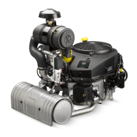
Remove Throttle Body (NEW UPDATED DESIGN Electronic Governor)
1. Disconnect TPS wire.
2. Loosen 2 screws securing lifting bracket and air cleaner bracket to intake manifold.
3. Remove nuts securing elbow and throttle body.
4. Cut nylon tie strap retaining GCU wiring harness to GCU wire tie-down bracket.
5. Unplug 4 pin GCU connector from main engine harness.
6. Lift wire assembly out from between engine and intake manifold.
7. Remove 3 screws securing GCU bracket.
8. Disconnect link clip from outboard end of DLA; remove spring and linkage.
9. Carefully lift and move air cleaner brackets/ECU/GCU up on front section of engine. Secure temporarily to access
and replace throttle body.
10. On earlier engines with separate intake air temperature (IAT) and MAP sensors, disconnect IAT sensor from
throttle body.
11. Disconnect breather tube from throttle body.
12. Disconnect throttle position sensor connector.
13. Disconnect vent hose from bottom of throttle body.
14. Slide throttle body off studs.
15. Reverse procedure to reassemble, torque fasteners to proper specifi cations. Air cleaner bracket screws to 11.3
N·m (100 in. lb.); Air cleaner elbow to throttle body nuts to 7.9 N·m (70 in. lb.).
Remove New Sealed (Bonded) GCU Module Wiring Harness Assembly (NEW UPDATED DESIGN Electronic
Governor)
1. Remove screws securing sealed (bonded) GCU module wiring harness assembly to GCU bracket.
2. Disconnect DLA wire.
3. Cut nylon tie strap retaining GCU wiring harness to GCU wire tie-down bracket.
4. Unplug 4 pin GCU connector from main engine harness. Use a blunt tool and remove GCU connector from valley
baffl e.
5. Lift new sealed (bonded) GCU module wiring harness assembly upward routing between intake manifold and
engine; wires come out through square hole in GCU bracket.
6. Reverse procedure to install. Torque screws to 2.1 N·m (19 in. lb.).