STEP
6
-
Piston, Connecting Rod Assemblies:
-
A.
Place flywheel loosely on crankshaft and tip engine using flywheel as supporting base.
B.
Separate rod caps from assemblies but be careful not to mix caps.
C.
Lightly oil bearings, crank pins, piston rings, then rotate rings so that gaps are not in line.
Use
ring compressor to install piston assemblies into cylinder bore.
Make sure raised
markings on connecting rods and caps face the front (flywheel) end.
Also, if arrow is
stamped on top of K482 piston, arrow must face direction of crankshaft rotation (clockwise
when facing flywheel).
Arrow stamping on early models only.
Gently push piston into bore
with hammer handle
--
do not pound into position.
STEP
7
-
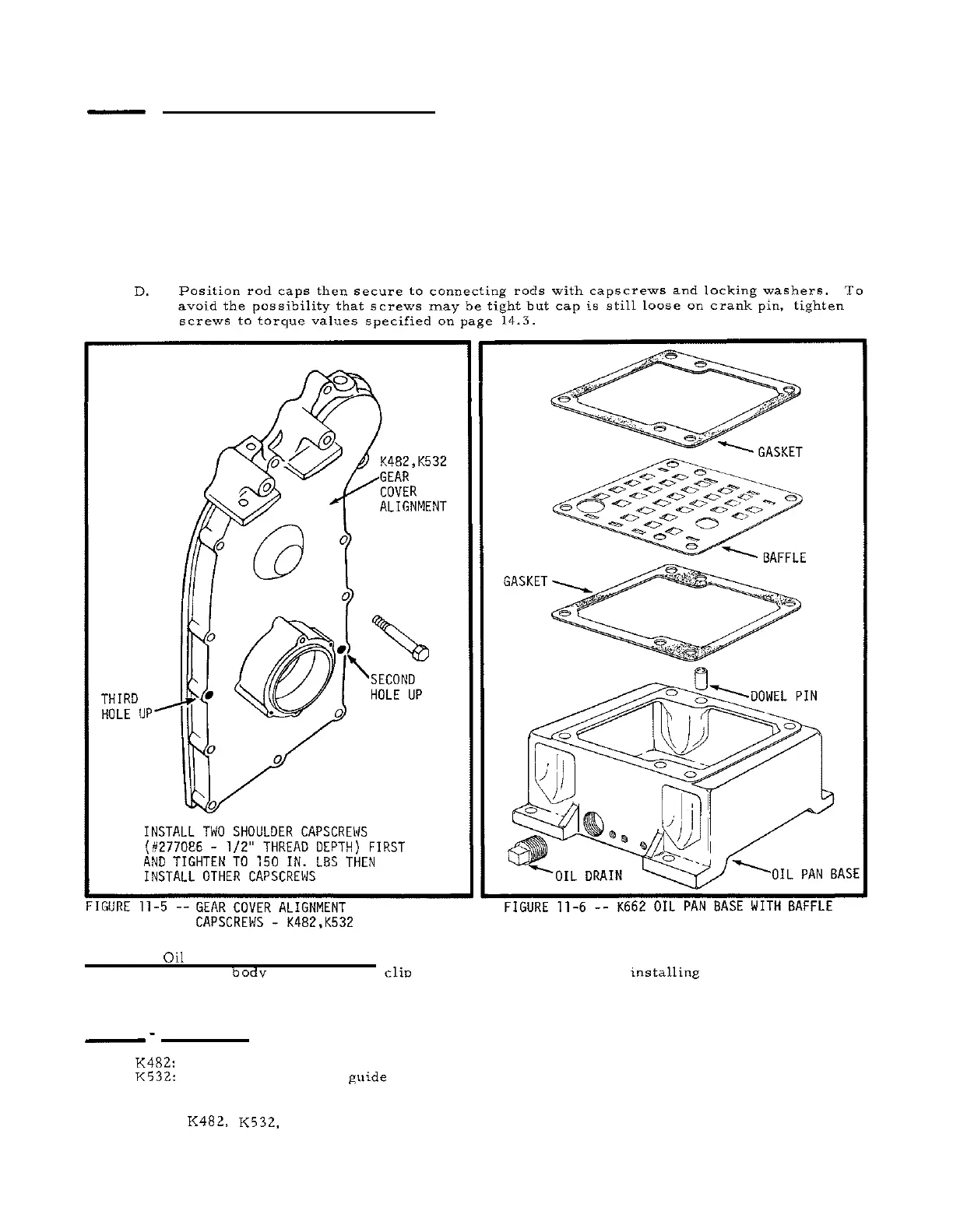
Oil Screen and Oil Pan Base:
Connect oil screen or strainer to oil pump body.
Thread oil
tube into
body then assemble clip and strainer to tube. After installine strainer, position new
-
.
oil pan gasket,
place dowel, then secure oil pan to block with oil pan capscrews.
If pan baffle
is used, position gasket
on
each side of baffle.
STEP
8
-
Gear Cover:
-
K482: Grease
seal to make
it slide easier then install new oil seal in cover, position
new
cover
K532: gasket then carefully guide cover over shaft.
Gently work cover when installing to prevent
damage to the seal.
Before inserting capscrews, position the blower housing support then
secure cover and support to block with the capscrews.
When installing gear cover on
K482,
K532,
make sure that the two shoulder screws are installed in locations shown
above to align cover.
Misalignment will cause stator damage.
11.4
 Loading...