Repair Service and Repair Manual
Lubricating system
Overview
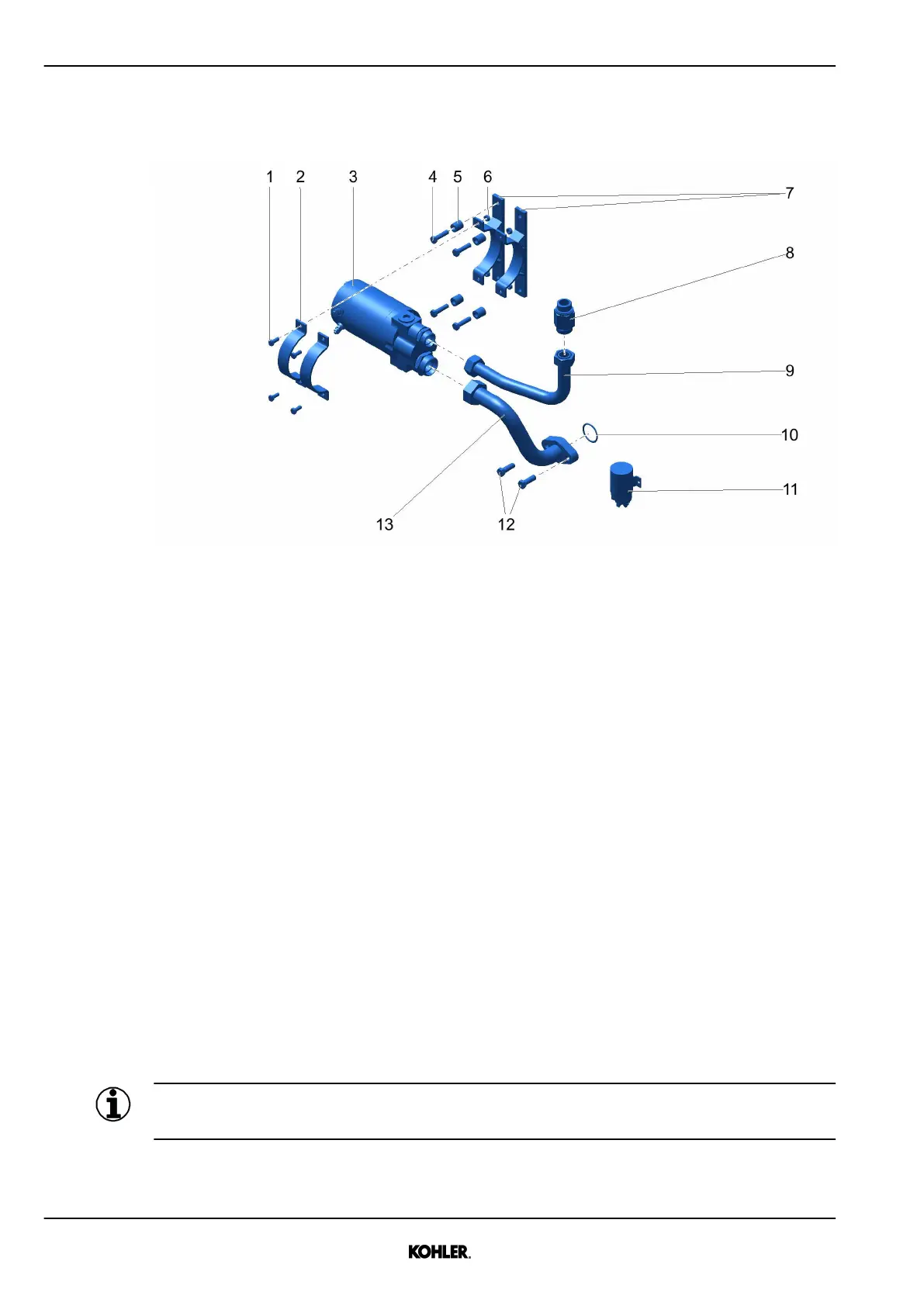
Fig. 217: Task overview
1 Screw (M8) 8 Return valve
2 Clamp 9 Oil line
3 Prelubricating pump 10 O-ring
4 Screw (M10) 11 Relay
5 Distance sleeve 12 Screw (M12)
6 Nut 13 Oil line
7 Holder
Removal
u Remove oil line 9.
u Remove return valve 8.
u Remove oil line 13 and screws 12.
u Remove o-ring 10.
u Remove screws 1.
u Remove clamps 2.
u Remove prelubricating pump 3.
u Remove screws 4, distance sleeves 5 and nuts 6.
u Remove holders 7.
Installation
Information
Do not install relay 11 on the engine.
u Install holders 7 with screws 4, distance sleeves 5 and nuts 6.
194
© 2021 by Kohler Co. All rights reserved.
KD62V12 33525088601_7_1 EN_US
2021-07
 Loading...