TP-6836 4/14 47Section 7 Bypass/Isolation
Section 7 Bypass/Isolation
7.1 Introduction
Hazardous voltage.
Will cause severe injury or death.
Only authorized personnel should
open the enclosure.
DANGER
Removing the transfer switch from bypass/isolation
models. Hazardous voltage can cause severe injury or
death. Bypass and isolate the transfer switch before removing
it from the enclosure. The bypass/isolation switch is
energized. Do not touch the isolation contact fingers or the
control circuit terminals.
The bypass/isolation switch provides the ability to
withdraw the transfer switch for testing, maintenance, or
service without interrupting power to the load.
Note: When the bypass switch is closed, the transfer
switch is inhibited from automatic operation. Be
sure to open the bypass switch and place the
transfer switch in automatic after any
maintenance or service.
7.2 Bypass/Isolation Switch
Components
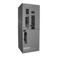
See Figure 7-1 for the locations of the following
components.
Manual Bypass Handle. The manual bypass handle
actuates the bypass operator. In the OPEN position, the
bypass normal and emergency contacts are open. In
the Bypass to Normal position, the load is connected to
Source N. In the bypass to emergency position, the load
is connected to Source E.
ATS Location Handle (150- to 400-amp switches only).
The position of the ATS location handle determines the
ATS mode of operation: AUTO, TEST, or isolate. The
ATS location handle can be moved only w hen the
manual bypass handle is in the bypass position.
Crank Mechanism (600- to 3000-amp switches only).
The crank mechanism determines the ATS mode of
operation: AUTO, TEST, or isolate. Turn the crank
mechanism clockwise to raise the ATS and
counterclockwise to lower the ATS through the three
positions. The crank mechanism can be rotated only
when the manual bypass handle is in the bypass
position.
Disconnect Switch. The disconnect switch controls
the ATS coil operation. In the AUTO position the ATS
operation is controlled by the logic c ontroller. In the
INHIBIT position, the logic controller cannot energize
the ATS coils.
1. Lamps
2. Logic controls
3. Disconnect s witch
4. Manual bypass handle
5. ATS location handle
1
2
3
4
5
6449
Figure 7-1 Bypass/Isolation Switch
(150--400 amp model shown)

 Loading...