TT-1403 4/16 7
3.2 KSS-J Models with Decision-Makerr
MPAC 750 Controllers
1. Verify that power has been disconnected as
described in Section 2, Installation Procedure.
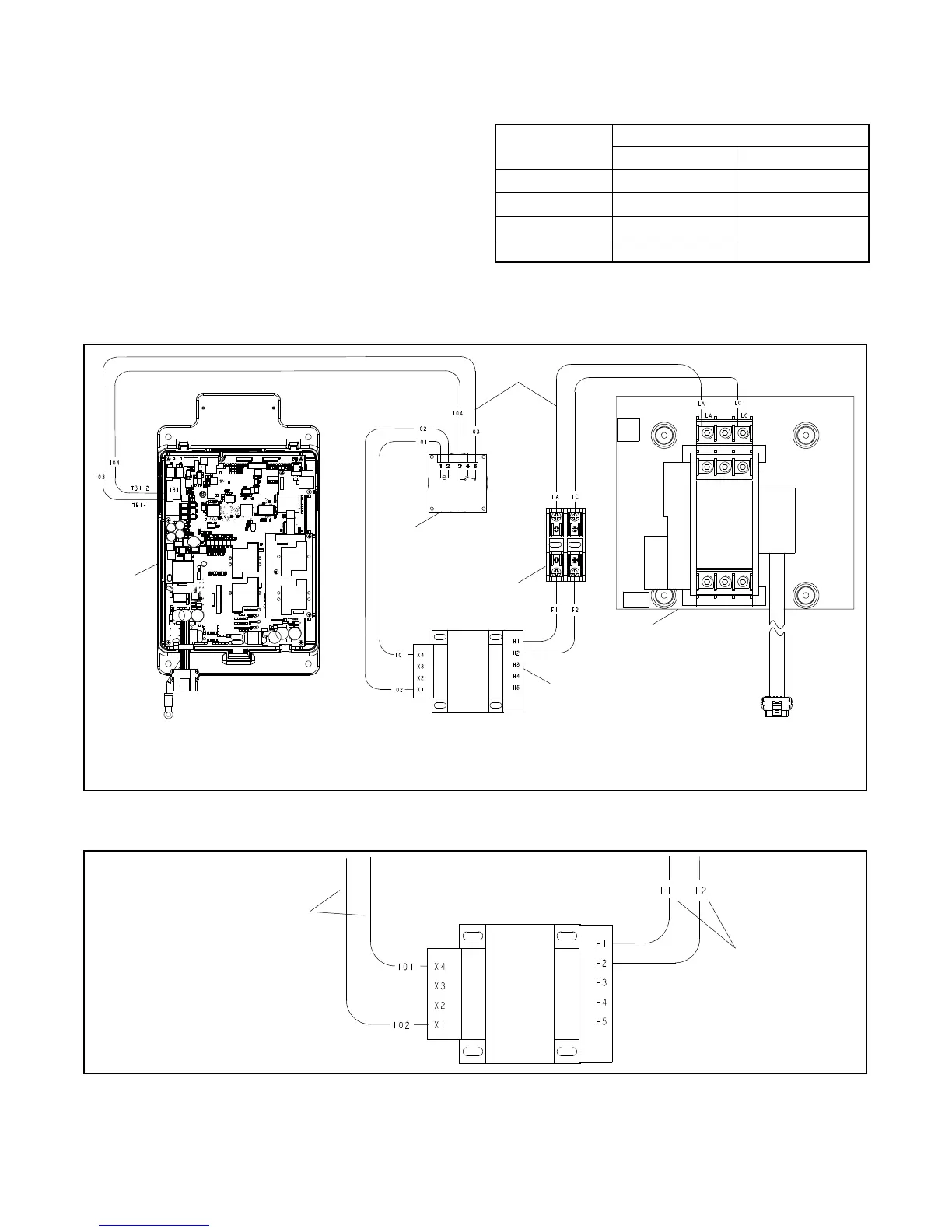
2. Use harness leads GM91325, supplied, to connect
the exercise kit according to the wiring diagram in
Figure 10. Connect the timer to the controller
(leads 103 and 104) and connect the fuse block to
the contactor (leads LA and LC). Use piggyback
terminals 233704 at the contactor if needed.
3. Connect the transformer to supply the correct
voltage to the timer. Configure the primary and
secondary transformer connections for the
corresponding system voltage. See Figure 9 and
Figure 11.
System Voltage
Transformer Connections
Primary Secondary
208 H1, H2 X1, X4
220--240 H1, H2 X1, X3
380--416 H1, H3 X1, X3
480 H1, H4 X1, X3
Figure 9 Transformer Wiring Configuration Chart
GM91312
1. Decision- M akerr MPAC 750 Controller
2. Harness GM91325
3. Timer GM64027
4. Fuse blocks X-6129-2 and X-6129-4
5. Contactor
6. Transformer GM40071
1
3
4
6
5
2
Figure 10 Wiring Diagram for KSS-J Models with Decision-makerr MPAC 750 Controller
GM91312
1. Primary Transformer
Connections
2. Secondary Transformer
Connections
2
1
Figure 11 Diagram Detail, Transformer Wiring Configuration (208 V shown; see Figure 9 for other voltages)