33
UAB KOMFOVENT we reserve the right to make changes without prior notice
DOMEKT_C8_guide_21-07
• Indoor humidity – this setting is necessary for estimating eciency of a pre-heater. When “Auto” setting is selected, in-
door humidity will be set automatically using an integrated humidity sensor and/or external humidity sensor connected
to B8 terminal of the controller (see “Installation Manual”). If the control panel is installed in an inappropriate location (or
is not used) and no outside humidity sensors are connected, uncheck the AUTO box and enter the indoor humidity in
the range of 10...90 %.
Wrong value of indoor humidity may cause antifreeze protection to malfunction and a counter-ow
heat exchanger to freeze.
• Stage numbers indicates the order of activation of heating/cooling devices. All units have an integrated electrical
heater, therefore it is factory-assigned as Stage 1. You can also assign an “external coil” (duct-mounted water heater/
cooler) or an “external DX device” (direct evaporation unit) as a stage. If an external coil is selected, you also must specify
its type: “Hot water” (used for heating), “Cold water” (used for cooling). If additional heating/cooling devices are not avail-
able, you do not want to use them or an electric heater, select “None”.
If you turn an electric heater o and do not use a duct-mounted heater, the desired air temperature
may not be reached when the outside air is cold.
• Allow dehumidication with cooling – this setting must be enabled to use a DX unit or duct-mounted water cooler to
dehumidify the supply air. An option to enter a value for desired humidity will appear in the settings of standard ventila-
tion modes (see Chapter 2.5.2).
AIR QUALITY – here you can activate and set-up air quality control which will be used in AUTO mode (see Chapter 2.5.2):
• Impurity control – turning on/o an impurity control function. At least one CO2 or VOC sensor must be connected to the
controller board to activate this function (see Chapter 2.5.2.). If ventilation by a weekly schedule is required, this function
must be turned o.
• Humidity control – turning on/o a humidity control function. Humidity control function requires a humidity sensor. If
no humidity sensor is connected to the controller board, sensor integrated in a control panel will be used for this purpose
(see Chapter 2.5.2.).
• Sensor 1 – specify the type of the sensor connected to a terminal B8 (see “Installation Manual”). If this sensor is not avail-
able, select “None”.
• Outside humidity – this option appears only if one of the sensors is of RH type (humidity sensor). If any of the connected
sensors are installed in the outdoor air ow, specify which one. If none of the installed humidity sensors measure the
outside humidity, select “None”.
• Minimum intensity – select ventilation intensity at which the unit will operate when air quality (impurity or humidity) is
good. If 0% is selected, the unit will stop when air impurity level is low.
• Maximum intensity – select ventilation intensity limit, under which the unit will operate when air quality (impurity or
humidity) exceeds a dened value.
• Check period – specify how often the unit shall turn on to check air quality, when minimum intensity is set to 0%.
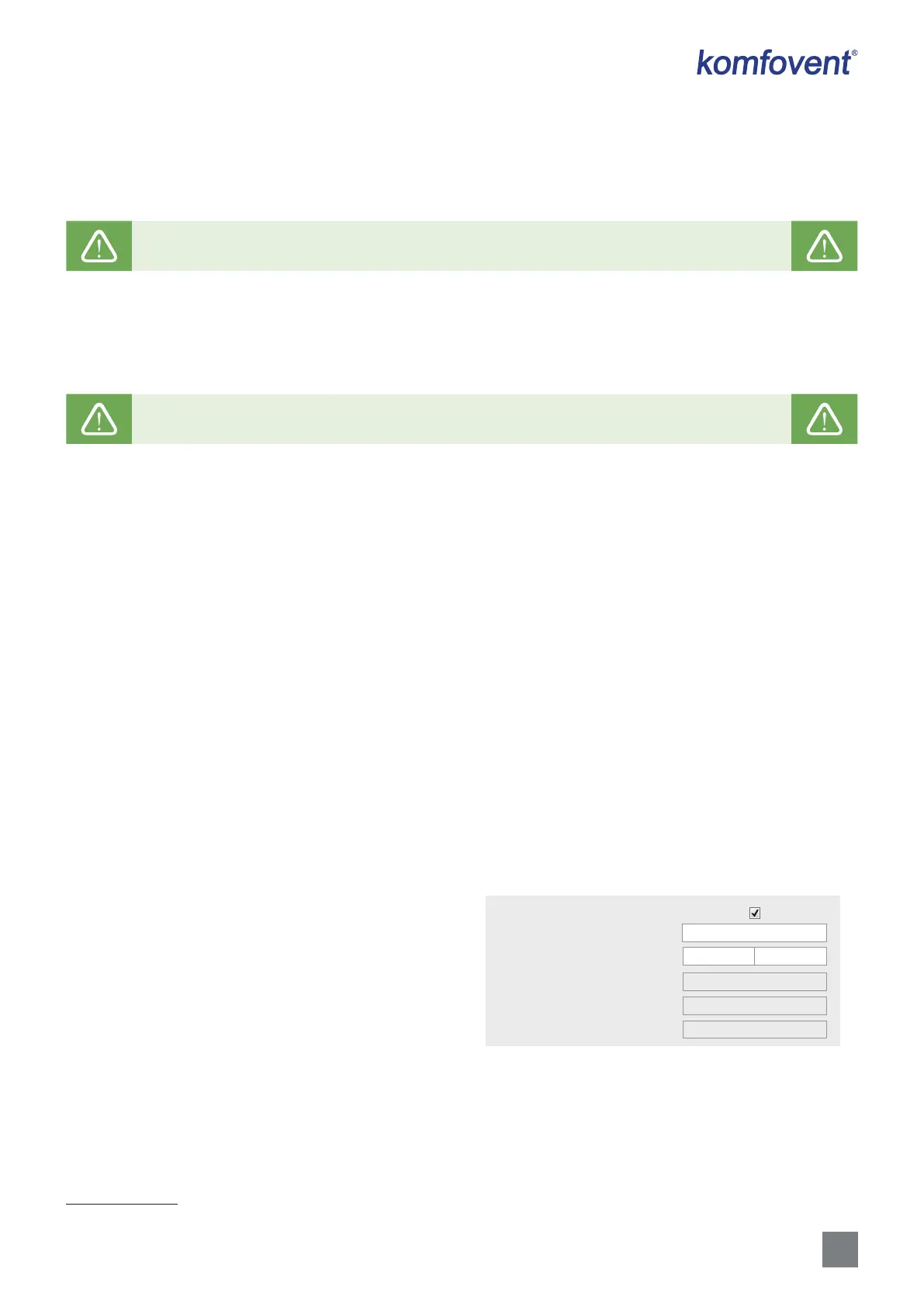
Fire damper
1
– parameters for the re damper system
tests can be set. It is possible to select either automatic or
manual re damper test. For automatic test, it is needed to set
testing interval, as well as time of the day, when the tests will
be performed. During re damper test, AHU will be stopped
for several minutes, re dampers opened and closed. Exter-
nal re damper controller will check are al the dampers func-
tioning normally and will give the signal for AHU to restart or
will indicate alarm message if something is wrong in the re
damper system.
FILTERS – once lters are replaced, calibrate new lters and conrm replacement in the unit.
CLOUD – Here it is possible to reset user password, used for log-in to Komfovent Control app, that controls AHU via
smartphone.
1
Available only if optional re damper controller is congured and connected. Refer to Fire damper controller manual for more information.
12
FIRE DAMPERS
Automatic test
Test period
Test time
7
00
Start
Manual test
-
-
Last test
Next test
 Loading...