14
453694/C
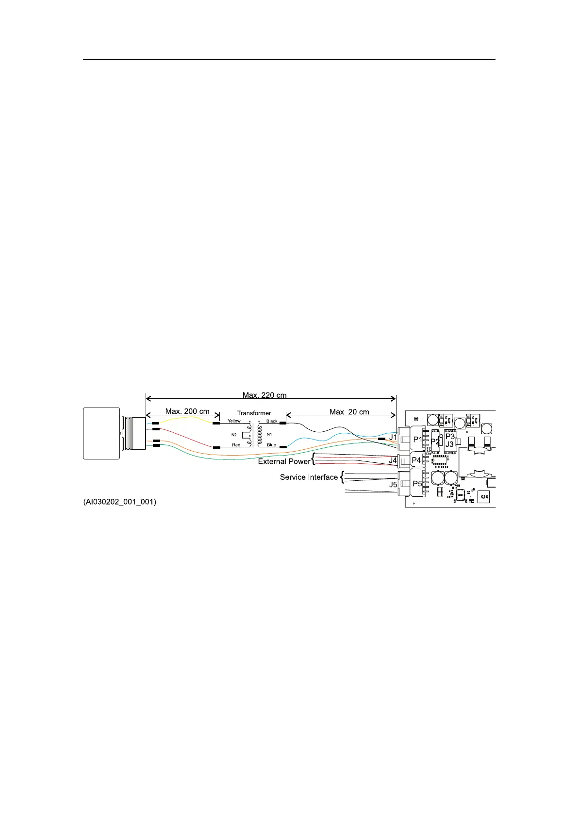
7Addcrimpterminalstotheendofthewires.
8InstallthecrimpterminalsinaMolex8-pinreceptacleaccordingtothecable
drawing.
aConnectthegreenwirestopin1and5onthereceptacle.
bConnecttheblackwirestopin3and7onthereceptacle.
cConnectthebluewirestopin4and8onthereceptacle.
dConnecttheorangewiretopin6onthereceptacle.
ThisisnowreceptacleJ1.
9ConnectreceptacleJ1toconnectorP1onthefrontofthePCB.
InstallingthetransducercablesTD40VMini
Cablescanbesuppliedwithanoptionalcablekit.
Prerequisites
TransducerconnectorpinoutJ1,page16
Thefollowingspecicitemsarerequiredforthistask:
•1xMolex8–pinreceptacle43025-0800
•7xMolexFemalecrimpterminal43030-0008
Procedure
1Useoneyellowwire(0.5mm
2
)andconnectthewhitewirefromthetransducerwith
theyellowwirefromthetransformer.
2Useoneredwire(0.5mm
2
)andconnecttheblackwirefromthetransducerwiththe
redwirefromthetransformer.
3Usetwoblackwires(0.5mm
2
)andconnectbothtotheblackwirefromthe
transformer.
4Usetwobluewires(0.5mm
2
)andconnectbothtothebluewirefromthe
transformer.
cNODEModemEmbedInstructionManual