EA 600 / Base version
156
857-164688 / E
Once all the system cables are connected and checked:
19 Take the appropriate safety measures, then replace the
fuses and apply power to the system.
20 Perform a system test to ensure the installation has been
conducted successfully.
Additional type 1 (842-093878)
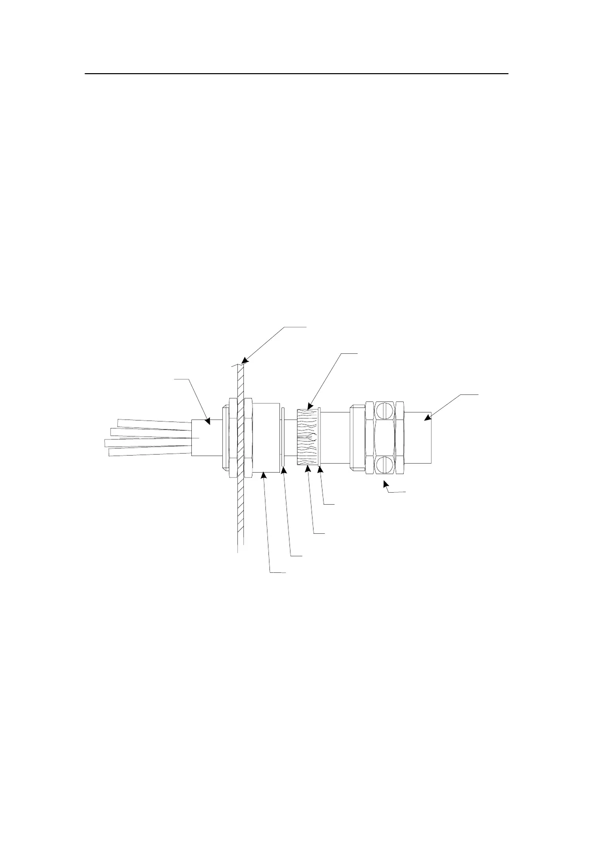
1 Mount the cable gland body, and tighten it with the nuts
on each side of the cabinet wall.
2 Slide the metal washers, the rubber gasket and the
compression nut onto the cable in the order indicated in
the figure.
→ Refer to figure 39.
Rubber gasket
Metal washer
Cable gland body
Compression nut
Cabinet wall
Inner cable
Outer screen bend backwards
over the rubber gasket
Cable
Metal washer
(CD3685/093878)
Figure 39 Cable gland, type 1 (842-093878)
3 Bend the screen over the rubber gasket.
4 Push the rubber gasket and the two metal washers
carefully into the cable gland body.
5 While holding the gland body to prevent it turning, and
pressing the cable into the gland, tighten the compression
nut onto the gland body.
Additional type 2 (541-093642)
1 Mount the cable gland body, and tighten it with the nuts
on each side of the cabinet wall.
 Loading...