Replacement procedures
67
857-164688 / E
5.2 General Purpose Transceiver (GPT)
procedures
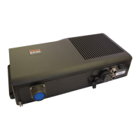
Overview
The Line Replaceable Units (LRUs) in the GPT are:
• TRX transmitter and transceiver board(s)
• DSP-6x
• I/O card
• Power supply
• Vicor power
Other devices:
• AC mains fuse, 2A slow
• DC fuse, 10A slow or fast
The replacement procedures for these parts are described in the
following disassembly and reassembly procedures.
The modules that are accessible, are described in this chapter.
Circuit boards and modules
Introduction
The system must be switched off prior to disassembly. Access is
gained by opening the top panel of the GPT. How to open the
GPT is described under the Disassembly procedure.
Disassembly procedure
1 Remove the mounted cables from the applicable circuit
boards.
2 Release the thumb-screws if required. (TRX boards are
mounted behind the front cover).
3 Pull the board/unit carefully out.
Reassembly procedure
1 Check links and switches on the new board and compare
to the old board.
2 Insert new circuit boards and modules in reverse order.
Mount the removed cables and the front covers.
3 Check that the circuit boards and modules have been
installed in their correct locations! (Refer to the applicable
pictures and drawings).




 To Next Page