GPT description and maintenance
55
857-164688 / E
TRX board
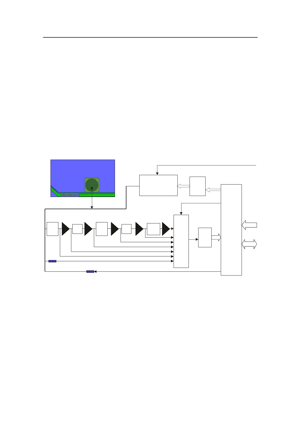
Purpose and description
The transmitter/receiver (TRX) board contains a full bridge 1 or
2 kW transmitter, a high precision receiver, a 12 bit AD
converter and digital control circuitry. The transducer connector
is located at the top of the board. Transmitter commands and
sample data are digitally communicated via the address/data-bus
at the bottom of the board.
How it works
Below is a simplified block diagram.
Figure 20 TRX board block diagram
Input
filter
BP
filter
Filter
U
TX
: 1000
- 70 dBW
P
L
D
TX-
Drivers
Test signal
M
U
X
Full-bridge
Transmitter
A/D
DATA
ADDR.
High Voltage
x10 x10 x10 x10
x10
1 or 2 Transceiver PCBs
BP
filter
(Measuring TX-Voltage and ref. for Phase measurement)
)
Filter
General Purpose Transceiver
Transducer
(CD 6757)
1 or 2 Transceiver PCBs




 To Next Page