Slide the sensor tube through the mounting clamps. Rotate the eyes into a position towards the web
and semi-tighten the clamps. The groove in sensor head shows the direction of light beam (opposite
side). Final adjustment is done with the help of the signal level display after the unit is powered up.
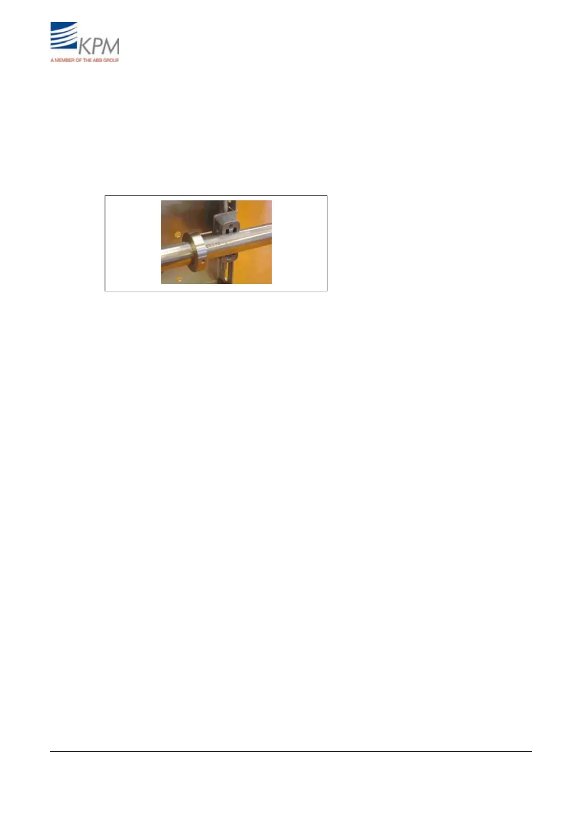
The light beam is directed to the measured web. Insert the pin of the position memory ring (fig.
2.5. ) into the hole in the clamp and tighten the stop screw. If the sensor is removed for maintenance
the memory ring ensures that the sensor head is positioned exactly in the same position as before the
removal.
Fig. 2.5. Position memory.
KB² Man W41100099V1.27August 2012