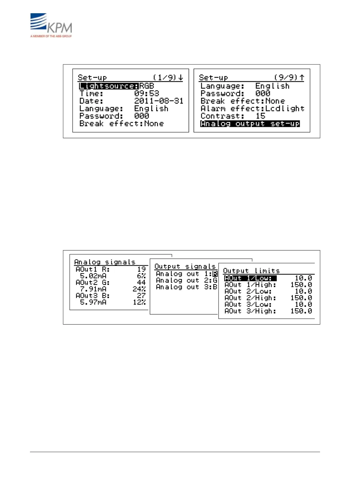
4.3. Set-up
Fig. 4.8. Setup displays.
– Light source: RGB (visible Red, Green, Blue) light is recommended in a normal application. IR
(Infrared) light is used in special cases, such as heavily steamy environment and/or long measure-
ment distance from the web.
– Date & time: Set date and time for data logging.
– Language: Select English/Finnish.
– Password: Set password. 000 = no password.
– Break effect: Select None, Beep, Lcd+Beep, Lcdlight (= blinking display).
– Alarm effect:Select None, Beep, Lcd+Beep, Lcdlight (= blinking display).
– Contrast: Set the display contrast (1 - 10), default = 10.
– Analog output setup: Output and mA-values are shown only, if the analog output board is in-
stalled.
Fig. 4.9. Analog output set-up.
– Analog output signals: On optional analog board there are three 4 - 20 mA analog outputs. You
can select any of the RGB signals and their combinations to each output. Menu is displayed only,
if board is installed.
– Analog output limits: Set the signal levels corresponding 4 mA (LOW) and 20 mA (HIGH) for
each analog output.
– Analog output filter: Select the dampening of the analog signals. The selected filtering time is
applied to all the 3 outputs.
– mA output error mode: When the self-diagnostics finds a failure the unit sets the outputs to the
selected mode. You can set the outputs to go to 22.5 or 3.5 mA, or to freeze to the last good
number, or to continue to show the measured values although they may be wrong (mode No
eff(ect)).
KB² Man W41100099V1.216August 2012