2. Installation
Note: Do not mount several fiber-optic sensor heads side by side; a mutual interference may occur. In-
frared dryer might also interference the measurement.
2.1. Delivery limits
Manufacturer supplied components:
– KB sensor head with position memory, 1 ea
– Mounting clamps, 2 ea
– Fiber-optic cable (6 m/20", 9 m/30" or 12 m/40"), 1 ea
– Display unit, 1 ea
– Flexible conduit for a fiber-optic cable protection (SS tubing, 25,4 mm / 1" OD), 1 ea
Options:
– Mounting rack.
– Analog output board.
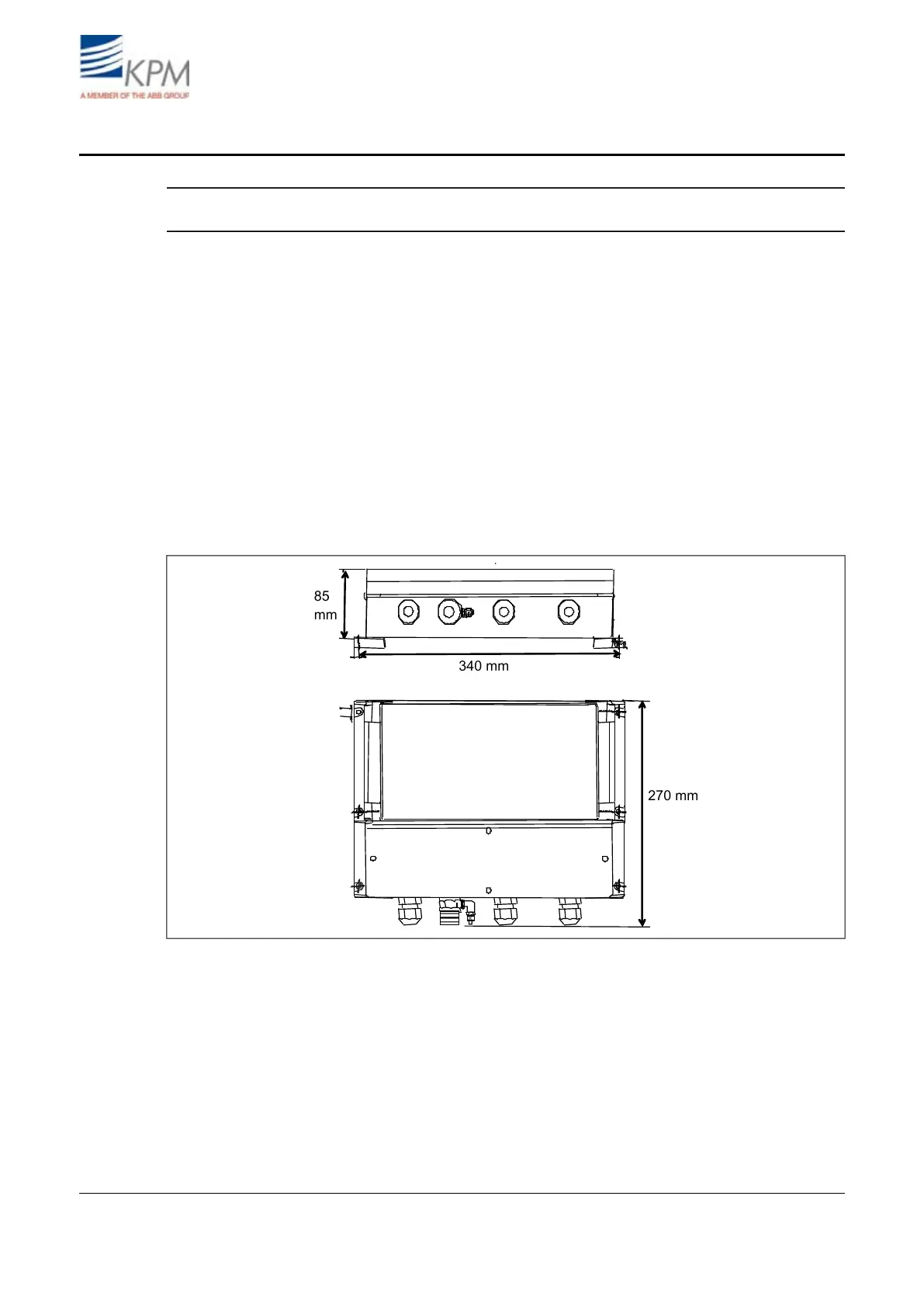
2.2. Display unit installation
Install the display unit to the wall outside the machine for easy access.
Fig. 2.1. Display unit dimensions (mm).
KB² Man W41100099V1.25August 2012