4.2. Configuration
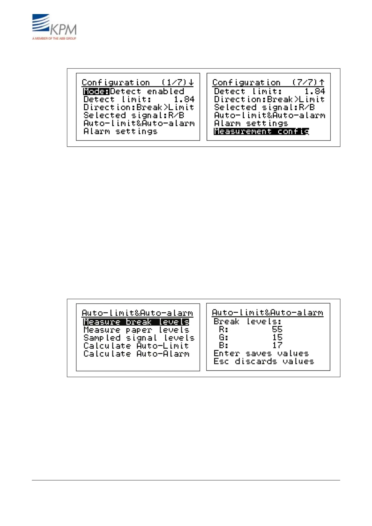
Fig. 4.3. Configuration menu.
(Operating) Mode: Select "Detect enabled" for normal operation. For maintenance select "Mainten-
ance" – it disables the break relay to prevent false break during the maintenance work.
Detect(ion) limit: Set the signal level trigger point for the break.
(Detect) Direction: Select, when the break is activated, if the signal level goes under ("Break <
Limit") or above ("Break > Limit") the detection limit.
Selected signal: One of the RGB-signals or combinations thereof can be selected for break detection.
The one, which gives the highest difference between the web-on (PAPER) and the web-off (BREAK)
situation is selected. In case IR light source is selected, then only IR is possible.
Auto-limit and Auto-alarm:
Auto-limit sets the signal type for break detection, detection level and direction, when performed.
Auto-alarm sets the alarm signal and alarm limits, when performed.
Fig. 4.4. Setting reference values for break levels.
KB records all the signal levels in BREAK/PAPER situations and stores them as reference values.
Measure break (signal) levels: Press right arrow. To store Break signal levels in KB memory press
"ENTER". "ESC" will escape without storing. Press "Sample" in front panel to average also signal
levels and enter this display, where break and paper values can be stored.
Measure paper (ON signal) levels Press right arrow. To store Paper ON signal levels in KB memory
by press "ENTER". "ESC" will escape without storing. Press "Sample" in front panel to average also
signal levels and enter this display, where break and paper values can be stored.
Sampled signal levels: Displays both stored signal levels (PAPER and BREAK).
KB² Man W41100099V1.213August 2012