1. Quick start-up guide
This quick guide leads the way to install, start-up and configure necessary parameters in the normal
cases.
1. PREPARING INSTALLATION
– Install fiber optic cable inside conduit. This is easier done when temperature is cool and conduit
is straight on the floor.
NOTE: DO NOT PULL FIBER OPTIC CABLE STRONGLY. It may break or cut or connector may get loose.
– Connect conduit to sensor head tube.
– Install sensor head mounting rack or mounting clamps.
2. Sensor unit installation
– Check that dry clean purge air is connected (pressure between 0.5 - 3.0 bar / 7-40 psi).
– Check that the eyelet holes are aimed at the web.
– Check that the sensor distance from the web is 10 – 30 cm ( 4 - 12").
– Check that the measurement point distance to paper edge is about 30 cm (12").
– Fix position preliminary. Tuning may change this slightly.
3. Display unit installation
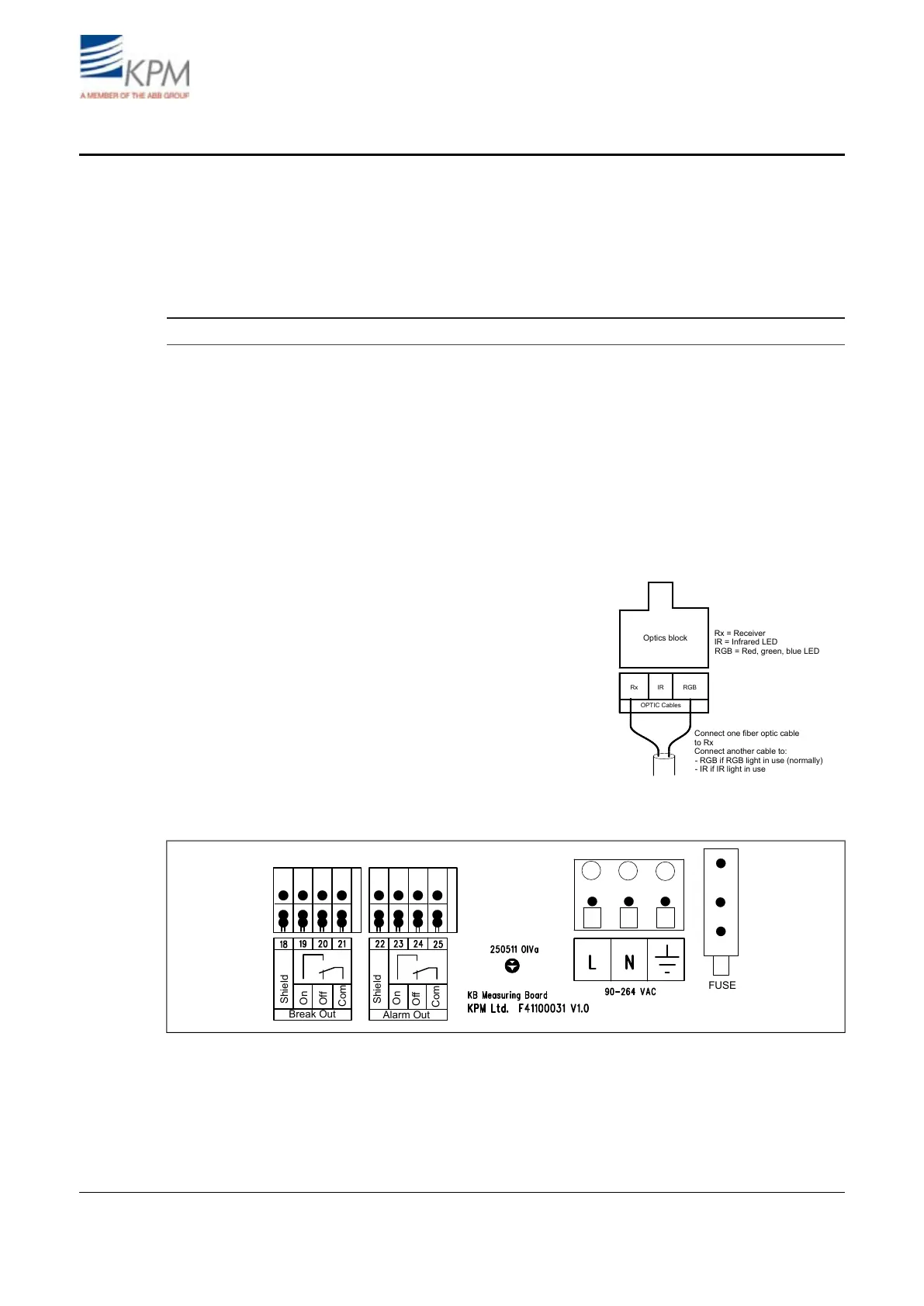
Rx IR RGB
OPTIC Cables
Optics block
Connect one fiber optic cable
to Rx
Connect another cable to:
Rx = Receiver
RGB = Red, green, blue LED
IR = Infrared LED
- RGB if RGB light in use (normally)
- IR if IR light in use
– Check that fiber optic conduit bushing is
tight.
– Check that fiber optic cable is connected
to the optics block:
- Other optic cable to RX.
- Another cable to RGB or IR.
– Check the wiring of the power supply.
– Check the wiring of break signal.
– Check the wiring of alarm signal.
Fig. 1.1. Fiber optic cable connection.
Break Out
Shield
Shield
On
On
Off
Off
Com
Com
Alarm Out
FUSE
Fig. 1.2. Wiring diagram.
2