Defining the FC‑404NET 4X4 Dante Interface
This section defines the FC‑404NET.
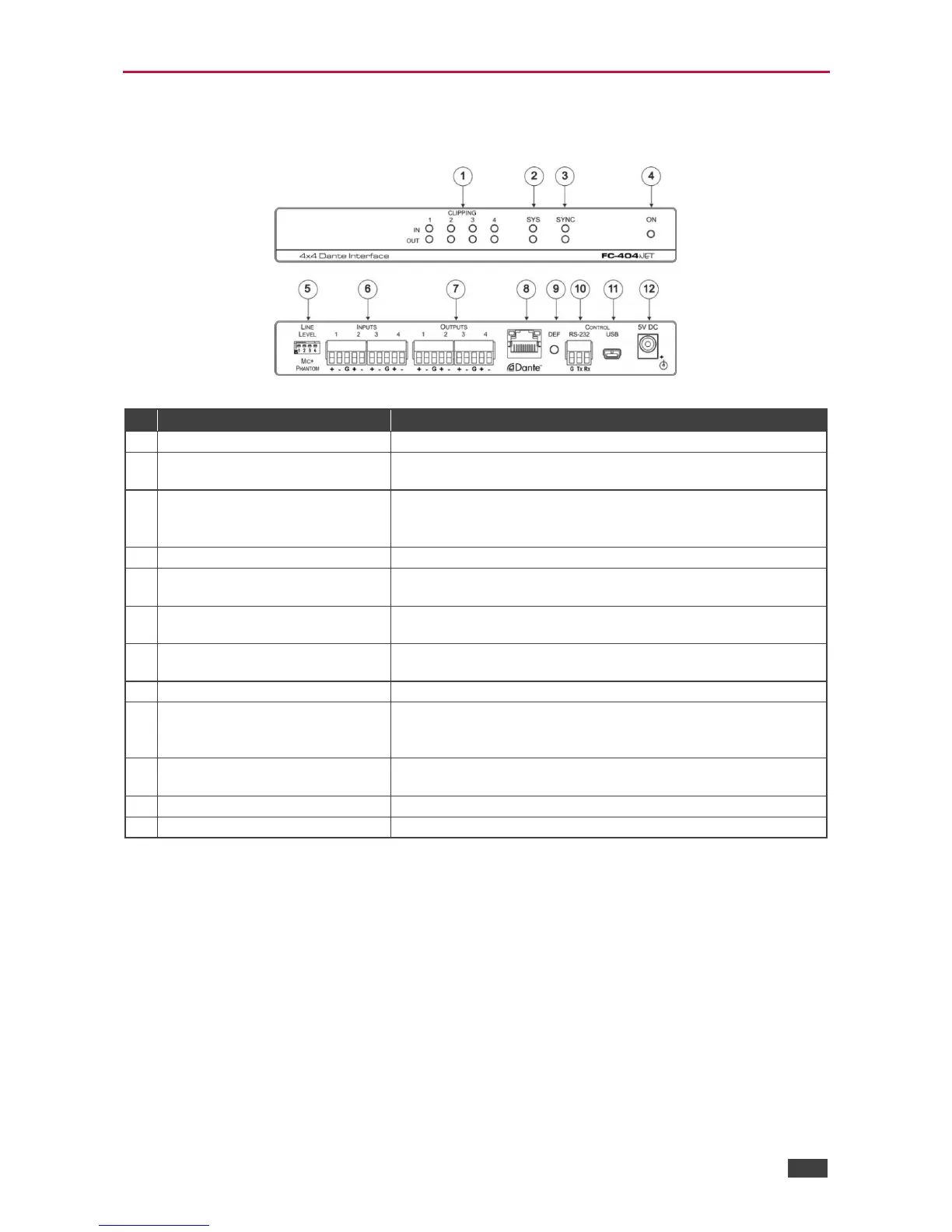
Figure 1: FC‑404NET 4X4 Dante Interface
CLIPPING 1-4, IN-OUT LEDs
Lights when in/out signal is clipped
Lights green when Dante network is available or red if an error
occurred
Lights green for digital audio normal operation.
Flashes green when this unit is the Master clock.
Lights red if an error has occurred.
Lights green when the unit is powered on
LINE LEVEL/MIC + PHANTOM
DIP-Switches (1 to 4)
Set up (OFF) for line level input, set down (ON) for mic level
input and +48v phantom supply to the microphones
INPUTS Terminal Block
Connectors (1 to 4)
Connect to balanced line-level audio sources 1-4, (+, –, G) (line
or mic levels)
OUTPUTS Terminal Block
Connectors (1 to 4)
Connect to balanced line-level audio acceptors 1-4, (+, –, G)
DANTE NET RJ-45 Connector
Connects to the IP network
To reset/reboot the device, press and release the button
To reset to factory settings, press and hold the button for 30
secs
CONTROL RS-232 3-pin
Terminal Block Connector
Connects to a control unit or PC running Protocol 3000
CONTROL Mini USB Connector
Connects to the power supply