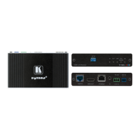
WP-789T, TP-789R, TP-789Rxr – Connecting WP-789T, TP-789R, TP-789Rxr
6. Connect the HDBT OUT RJ-45 Connector on the TP-780Txr rear panel to the HDBT IN
RJ-45 Connector on the TP-789R/TP-789Rxr rear panel.
7. Connect a LAN-enabled device (for example, FC-7 control gateway) to the Ethernet
Connector on the TP-789Rxr rear panel.
8. Connect the power adapter to the 48V DC Power Terminal Block on TP-780Txr rear
panel and to the mains electricity (not shown in Figure 6).
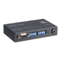
Connecting to Device via RS-232
You can connect to WP-789T, TP-789R, TP-789Rxr via the RS-232 3-pin Terminal Block
Connector. The RS-232 connection can be used in the following ways:
• Serial Communication Extension – Connect a serial controller, for example SL-240C for
extending RS-232 communication to the other end of the HDBaseT extension to control
an external device.
• Firmware Upgrade – Contact your local technical support.
To connect to WP-789T, TP-789R, TP-789Rxr via RS-232 from a D-sub connector:
• Pin 2 to the Tx pin on the WP-789T, TP-789R, TP-789Rxr
RS-232 terminal block.
• Pin 3 to the Rx pin on the WP-789T, TP-789R, TP-789Rxr
RS-232 terminal block.
• Pin 5 to the G pin on the WP-789T, TP-789R, TP-789Rxr
RS-232 terminal block.
Connecting to WP-789T IR Terminal Block
WP-789T can either emit or receive an IR signal. This section explains how to connect an IR
emitter or sensor to the WP-789T IR terminal block in order to achieve the required
configuration.