1 Supplementary Operating Manual
4 of 48
AmaControl
2301.83/04-EN
1 Supplementary Operating Manual
1.1 General
This supplementary operating manual accompanies the installation/operating
manual. All information contained in the installation/operating manual must be
observed.
Table1: Relevant operating manuals
Type series Reference number of the installation/operating
manual
Amacontrol 2301.82
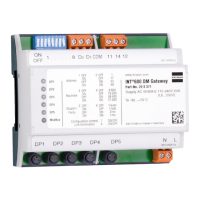
1.2 INT 600 DM Gateway
1.2.1 Functional description of the INT 600 DM Gateway
AmaControl devices can be read in and converted to the Modbus protocol via the
five DP inputs. Built-in LEDs indicate the current activities of the gateway.
The INT 600 DM Gateway has the following features:
▪ Direct plug-type connection of AmaControl
▪ Simple analysis of the interfaces during data transmission by means of function
LEDs
▪ Straightforward mounting for control cabinet installation
▪ Wide range of applications due to dual-voltage power supply unit
▪ Extended temperature range for use in outdoor control cabinets
▪ Remote reset possible
▪ Air gap: no possibility of accessing the protection devices from the Internet
▪ Connection to customer's control system (Modbus RTU protocol)
▪ Shock and vibration resistant
▪ cURus approval
Modbus
The Modbus interface supports the standard Modbus function code.
Table2: Standard Modbus function code
Standard Modbus function code Description
0x04 Read input register
0x03 Read holding register
0x10 Preset multiple registers
Overview of flashing code
Table3: Modbus flashing codes
Modbus Description
Steady green Device switched ON
Flashing green Initialisation phase
Flashing yellow Valid data telegrams are being received
for the set address
Flashing red Error during data transmission
Table4: DP flashing codes
DP Description
Flashing yellow Valid data telegrams are being received
from AmaControl
 Loading...