1 Supplementary Operating Manual
20 of 48
AmaControl
2301.83/04-EN
1.4.2 Modbus protocol, AmaControl 4 (Modbus interface)
NOTE
AmaControl 4 has an integrated Modbus RTU interface. Alternatively, AmaControl
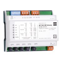
4 can be read out using the INT 600 DM Gateway.
Table14: Modbus Protocol, AmaControl 4
Start End Description Data type
8192 8192 High byte: visual ID
Low byte: reserved
u 16bit
8193 8193 High (12 bit): article main number
Low (4-bit): reserved
u 16bit
8194 8195 Consecutive serial number within the article number
Low word first
u 32bit
8198 8198 Fault message
Bit 0: 0 = no fault, 1 = at least one fault currently present
u 16bit
8199 8199 Operating status
Bit 0 – motor status: 1 = motor running
Bit 6 – alarm relay
Bit 7 – warning relay
Bit 8 – reset input
Bit 9 – reset key
{1=active}
u 16bit
8206 8206 Software revision
High byte: major software revision number
Low byte: minor software revision number, displayed: major. minor (e.g.
1.02)
u 16bit
8207 8207 Function variant
0 = engineering sample
1-9 = variants
u 32bit
8210 8210 Article number variants
If value < 10000
"S" [value]
If value > 10000
"P" [value - 10000]
u 16bit
8211 8211 Voltage key
13 = 24VDC
20 = 24VAC/DC
22 = 115-230V AC
31 = 24VAC
41 = 115VAC
52 = 230VAC
u 16bit
8212 8213 Total number of fault trips
Low word first
u 32bit
8214 8215 Total number of pump starts
Low word first
u 32bit
8216 8216 Number of seconds of the current hour (internal time) 0-3599s u 16bit
8217 8217 Remaining delay period. Estimated time before the motor can be re-
started
0..65,533 seconds
65,535 = interlocked tripping
65,534 = time undefined
u 16bit
8218 8219 Time stamp
Seconds elapsed since 01/01/1970 00:00:00,
POSIX format
u 32bit
8220 8221 Time stamp of last switching operation as per operating routine
Seconds elapsed since 01/01/1970 00:00:00,
POSIX format
u 32bit
 Loading...